
Page 18 - A Practical Companion to Reservoir Stimulation
P. 18
PRACTICAL COMPANION TO RESERVOIR STIMULATION
EXAMPLE A-3
(3.14) (3.068)* (13,200) (4 x
Calculation of the Permeability of a Tight Reservoir C=
from a Short-Duration Pressure Buildup Well Test (4) (144) (5.615)
= 4.8 x bbl/psi. (A-10)
This example demonstrates the method to estimate the res-
ervoir permeability from a very short-duration pressure From Eq. 1-101,
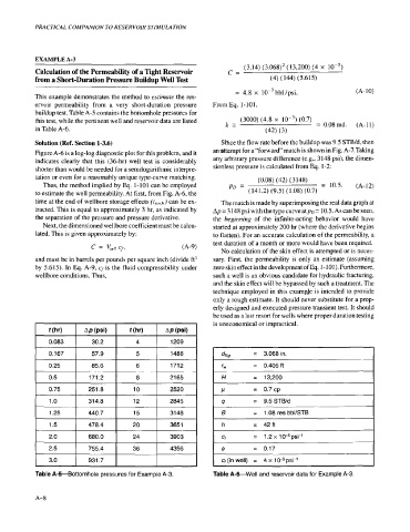
buildup test. Table A-5 contains the bottomhole pressures for
this test, while the pertinent well and reservoir data are listed k= (3000) (4.8 x (0.7) = 0.08md. (A-11)
in Table A-6. (42) (3)
Solution (Ref. Section 1-3.6) Sihce the flow rate before the buildup was 9.5 STB/d, then
Figure A-6 is a log-log diagnostic plot for this problem, and it an$tempt for a “forward” match is shown in Fig. A-7. Taking
indicates clearly that this (36-hr) well test is considerably any arbitrary pressure difference (e.g., 3 148 psi), the dimen-
shorter than would be needed for a semilogarithmic interpre- sionless pressure is calculated from Eq. 1-2:
tation or even for a reasonably unique type-curve matching. (0.08) (42) (3 148)
Thus, the method implied by Eq. 1-101 can be employed PD = z 10.5. (A-12)
to estimafe the well permeability. At first, from Fig. A-6, the (141.2) (9.5) (1.08) (0.7)
time at the end of wellbore storage effects (re.w.,J can be ex- The match is made by superimposing the real data graph at
tracted. This is equal to approximately 3 hr, as indicated by Ap = 3 148 psi with the type curve atpD = 10.5. As can be seen,
the separation of the pressure and pressure derivative. the beginning of the infinite-acting behavior would have
Next, the dimensioned wellbore coefficient must be calcu- started at approximately 200 hr (where the derivative begins
lated. This is given approximately by: to flatten). For an accurate calculation of the permeability, a
c = v,,, Cf, 04-9) test duration of a month or more would have been required.
No calculation of the skin effect is attempted or is neces-
and must be in barrels per pounds per square inch (divide ft’ sary. First, the permeability is only an estimate (assuming
by 5.615). In Q. A-9, cf is the fluid compressibility under zero skin effect in the development ofEq. 1- 101). Furthermore,
wellbore conditions. Thus. such a well is an obvious candidate for hydraulic fracturing,
and the skin effect will be bypassed by such a treatment. The
technique employed in this example is intended to provide
only a rough estimate. It should never substitute for a prop-
erly designed and executed pressure transient test. It should
be used as a last resort for wells where proper duration testing
is uneconomical or impractical.
I I I I
~
dtkl = 0.406 ft
= 3.068 in.
1 IH = 13,200
rW
P
I
= 0.7 CP
9.5 STBfd
1.08 res bbl/STB
- 42ft
I Ct = 1.2 x 1 0-5 psi-’
I 4 = 0.17
I 1 931.7 I I 1
I
3.0
Table A-5-Bottomhole pressures for Example A-3. Table A-&Well and reservoir data for Example A-3.
A- 8