
Page 71 - A Practical Companion to Reservoir Stimulation
P. 71
DESIGN AND MODELING OF PROPPED FRACTURES
EXAMPLE E-7
Integration of Eq. 8-46 from t = tpod to t = rjresults in
Calculation of the Ramped Proppant Schedule
and Total Proppant Injected
Assuming that ti (total injection time) is 7 hr, the rpUd is 3.5 hr,
and the efficiency is 0.35, calculate the ramped proppant
schedule for three end-of-job slurry concentrations, cf (6, 10
and 16 ppg). Calculate the total mass of proppant if the (E-35)
injection rate is 40 BPM.
Thus, the “average” slurry concentrations would be 4.05,
Solution (Ref. Section 8-2.6) 6.76 and 10.8 ppg, respectively.
As shown in Example E-6, the pad volume can be readily FOF 1 gal of slurry there are cI, lb of proppant. If this quan-
calculated if the efficiency is known. The end of the pad in- tity is divided by the density of the proppant (e.g., 165 lb/ft3)
jection marks the beginning of the ramped proppant schedule. and converted into gallons, then this would be the volumetric
The slurry concentration, c,,(t) in pounds per gallon (ppg), fraction of proppant:
is given by Eqs. 8-45 and 8-46. For example, if cr= 6 ppg,
then from Eq. 8-45, (E-36)
I - 0.35 Thus, for the three cases at hand, the “average” volumetric
.~
~
E = ~ = 0.48, (E-33)
1 + 0.35 fractions of proppant are 0.18, 0.3 1 and 0.49, respectively.
and from Eq. 8-46, During the 3.5 hr of pumping proppant, a total of (3.5)(60)
(40)(42) = 352,800 gal were injected, and the masses of
proppant would be
(E-34)
M, = CIJ v, . (E-37)
At t = 3.5 hr, of course, c,(t) = 0. At t = 4 hr, then Therefore, the masses of proppant are 1.43 x lo6 lb, 2.38 x
c,,(t) = 2.4 ppg. 1061b and 3.81 x lo6 lb, respectively.
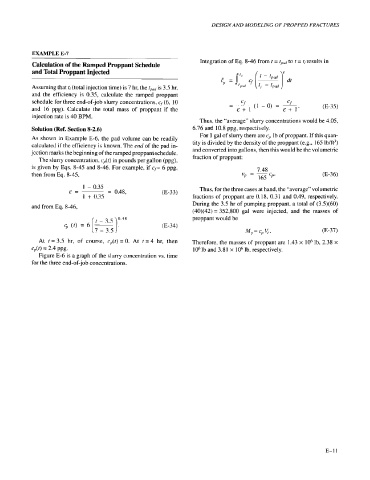
Figure E-6 is a graph of the slurry concentration vs. time
for the three end-of-job concentrations.