
Page 39 - A Practical Introduction to Optical Mineralogy
P. 39
THE MICROSCOPIC STUDY OF MINERALS POINTS ON USE OF MICROSCOPE
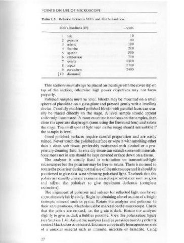
that a load of 100 grams should be applied for 15 seconds. The size of Table 1.2 Relation between VHN and Moh' s hardness.
the resulting square shaped impression depends on the hardness of the
mineral: Moh's hardness (H) - VHN
VHN = 1854 X load
dz kglmm 2
1 talc 10
2 gypsum 40
where the load is in kilograms and d is the average length of the 3 calcite 100
4 fluorite 200
diagonals of the impression in microns.
5 apatite 500
Hardness is expressed in units of pressure, that is, force per unit area.
6 orthoclase 750
Thus the microindentation hardness of pyrite is written:
7 quartz 1300
8 topaz 1700
pyrite, VHN 100 = 1027-1240 kglmm 2 9 corundum 2400
[10 diamond]
The subscript 100 may be omitted as this is the standard load. As VHN
values are always given in kglmm this is also often omitted.
2
Thin sections must always be placed on the stage with the cover slip on
The determination of hardness is a relatively imprecise technique, so
an average of several indentations should be used. Tables of VHN top of the section, otherwise high power objectives may not focus
properly.
usually give a range in value for a mineral, taking into account variations
du~ to compositi~n.al variations, anistropy of hardness and uncertainty. Polished samples must be level. Blocks may be mounted on a small
sphere of plasticine on a glass plate and pressed gently with a levelling
Br~ttleness, plastiCity and elasticity control the shape of the inden-
tatiOns, and as the shape can be useful in identification the COM device. Carefully machined polished blocks with parallel faces can usu-
r~commends that indentation shape (using the abbreviations given in ally be placed directly on the stage. A level sample should appear
Fig. 1.10) be given with VHN values. uniformly illuminated. A more exact test is to focus on the samples, then
close the aperture diaphragm (seen using the Bertrand lens) and rotate
There is a reasonable correlation between VHN and Moh's scratch
hardness as shown in Table 1.2. the stage. The small spot of light seen as the image should not wobble if
the sample is level.
Good polished surfaces require careful preparation and are easily
1.10 Points on the use of the microscope (transmitted and ruined. Never touch the polished surface or wipe it with anything other
reflected light) than a clean soft tissue, preferably moistened with alcohol or a pro-
prietary cleaning fluid. Even a dry tissue can scratch some soft minerals.
Always focus using low power first. It is safer to start with the specimen Specimens not in use should be kept covered or face down on a tissue.
The analyser is usually fixed in orientation on transmitted-light
surface close to the objective and lower the stage or raise the tube to
achieve the position of focus. microscopes but the polariser may be free to rotate. There is no need to
rotate the polariser during normal use of the microscope and it should be
positioned to give east- west vibrating polarised light. To check that the
polars are exactly crossed examine an isotropic substance such as glass
and adjust the polariser to give maximum darkness (complete
extinction).
The alignment of polariser and anlyser for reflected light can be set
p sf
(perfect) (slightly fractured) (fractured) approximately fairly easily. Begin by obtaining a level section of a bright
i otropic mineral such as pyrite. Rotate the analyser and polariser to
their zero positions, which should be marked on the microscope. Check
that the polars are crossed, i.e. the grain is dark. Rotate the analyser
slightly to give as dark a field as possible. View the polarisation figure
Figure 1.10 (see Section 1.4 ). Adjust the analyser (and/or polariser) until a perfectly
Indentation centred black cross is obtained. Examine an optically homogeneous area
cc cv
shapes. (concave) (convex) of a uniaxial mineral such as ilmenite, niccolite or hematite. Using
26
27