
Page 107 - ARM Based Microcontroller Projects Using MBED
P. 107
7.7 PROJECT 4—ROTATING LEDs 93
FIG. 7.24 The LED pattern.
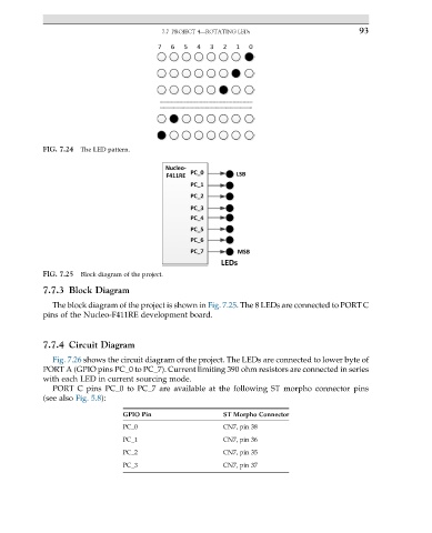
FIG. 7.25 Block diagram of the project.
7.7.3 Block Diagram
The block diagram of the project is shown in Fig. 7.25. The 8 LEDs are connected to PORT C
pins of the Nucleo-F411RE development board.
7.7.4 Circuit Diagram
Fig. 7.26 shows the circuit diagram of the project. The LEDs are connected to lower byte of
PORT A (GPIO pins PC_0 to PC_7). Current limiting 390 ohm resistors are connected in series
with each LED in current sourcing mode.
PORT C pins PC_0 to PC_7 are available at the following ST morpho connector pins
(see also Fig. 5.8):
GPIO Pin ST Morpho Connector
PC_0 CN7, pin 38
PC_1 CN7, pin 36
PC_2 CN7, pin 35
PC_3 CN7, pin 37