
Page 104 - ARM Based Microcontroller Projects Using MBED
P. 104
90 7. USING THE Mbed WITH SIMPLE PROJECTS
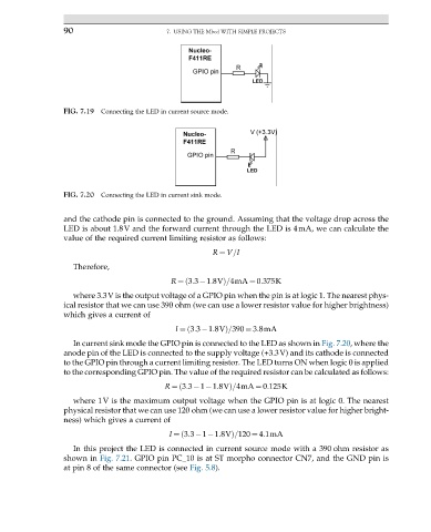
FIG. 7.19 Connecting the LED in current source mode.
FIG. 7.20 Connecting the LED in current sink mode.
and the cathode pin is connected to the ground. Assuming that the voltage drop across the
LED is about 1.8V and the forward current through the LED is 4mA, we can calculate the
value of the required current limiting resistor as follows:
R ¼ V=I
Therefore,
R ¼ 3:3 1:8VÞ=4mA ¼ 0:375K
ð
where 3.3V is the output voltage of a GPIO pin when the pin is at logic 1. The nearest phys-
ical resistor that we can use 390 ohm (we can use a lower resistor value for higher brightness)
which gives a current of
I ¼ 3:3 1:8VÞ=390 ¼ 3:8mA
ð
In current sink mode the GPIO pin is connected to the LED as shown in Fig. 7.20, where the
anode pin of the LED is connected to the supply voltage (+3.3V) and its cathode is connected
to the GPIO pin through a current limiting resistor. The LED turns ON when logic 0 is applied
to the corresponding GPIO pin. The value of the required resistor can be calculated as follows:
R ¼ 3:3 1 1:8VÞ=4mA ¼ 0:125K
ð
where 1V is the maximum output voltage when the GPIO pin is at logic 0. The nearest
physical resistor that we can use 120 ohm (we can use a lower resistor value for higher bright-
ness) which gives a current of
I ¼ 3:3 1 1:8VÞ=120 ¼ 4:1mA
ð
In this project the LED is connected in current source mode with a 390 ohm resistor as
shown in Fig. 7.21. GPIO pin PC_10 is at ST morpho connector CN7, and the GND pin is
at pin 8 of the same connector (see Fig. 5.8).