
Page 103 - ARM Based Microcontroller Projects Using MBED
P. 103
7.6 PROJECT 3—FLASHING AN EXTERNAL LED 89
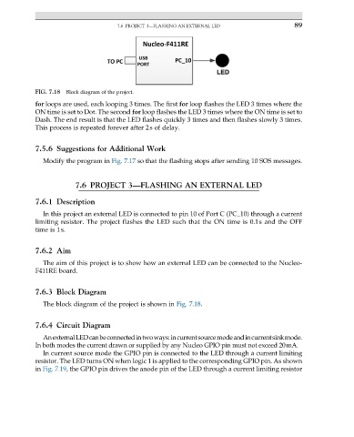
FIG. 7.18 Block diagram of the project.
for loops are used, each looping 3 times. The first for loop flashes the LED 3 times where the
ON time is set to Dot. The second for loop flashes the LED 3 times where the ON time is set to
Dash. The end result is that the LED flashes quickly 3 times and then flashes slowly 3 times.
This process is repeated forever after 2s of delay.
7.5.6 Suggestions for Additional Work
Modify the program in Fig. 7.17 so that the flashing stops after sending 10 SOS messages.
7.6 PROJECT 3—FLASHING AN EXTERNAL LED
7.6.1 Description
In this project an external LED is connected to pin 10 of Port C (PC_10) through a current
limiting resistor. The project flashes the LED such that the ON time is 0.1s and the OFF
time is 1s.
7.6.2 Aim
The aim of this project is to show how an external LED can be connected to the Nucleo-
F411RE board.
7.6.3 Block Diagram
The block diagram of the project is shown in Fig. 7.18.
7.6.4 Circuit Diagram
AnexternalLEDcanbeconnectedintwoways:incurrentsourcemodeandincurrentsinkmode.
In both modes the current drawn or supplied by any Nucleo GPIO pin must not exceed 20mA.
In current source mode the GPIO pin is connected to the LED through a current limiting
resistor. The LED turns ON when logic 1 is applied to the corresponding GPIO pin. As shown
in Fig. 7.19, the GPIO pin drives the anode pin of the LED through a current limiting resistor