
Page 434 - ARM Based Microcontroller Projects Using MBED
P. 434
420 17. STM32 NUCLEO EXPANSION BOARDS
CN10
ST Morpho connector CN9
Arduino UNO R3 connector
CN5
Arduino UNO R3 connector D3
Fault LED (red)
D1-D2
R20-R17
Power output
REF select operation LEDs (yellow)
J2 DC motor A
phases connector
U1 TP2
STSPIN250 DC driver
V motor testpoint
J1
Power motor
connector 10V max
TP3 TP1
VDD testpoint
Ground testpoint
CN6 CN8
Arduino UNO R3 connector
Arduino UNO R3 connector
CN7
ST Morpho connector
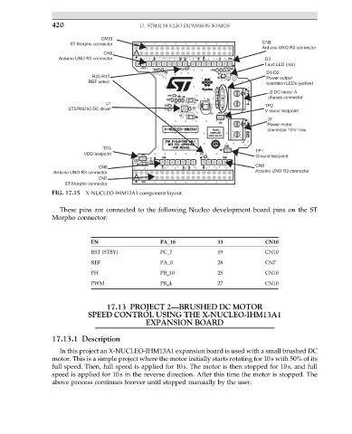
FIG. 17.15 X-NUCLEO-IHM13A1 component layout.
These pins are connected to the following Nucleo development board pins on the ST
Morpho connector:
EN PA_10 33 CN10
RST (STBY) PC_7 19 CN10
REF PA_0 28 CN7
PH PB_10 25 CN10
PWM PB_4 27 CN10
17.13 PROJECT 2—BRUSHED DC MOTOR
SPEED CONTROL USING THE X-NUCLEO-IHM13A1
EXPANSION BOARD
17.13.1 Description
In this project an X-NUCLEO-IHM13A1 expansion board is used with a small brushed DC
motor. This is a simple project where the motor initially starts rotating for 10s with 50% of its
full speed. Then, full speed is applied for 10s. The motor is then stopped for 10s, and full
speed is applied for 10s in the reverse direction. After this time the motor is stopped. The
above process continues forever until stopped manually by the user.