
Page 437 - ARM Based Microcontroller Projects Using MBED
P. 437
17.14 PROJECT 3—BRUSHED DC MOTOR SPEED CONTROL USING A POTENTIOMETER 423
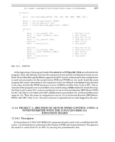
FIG. 17.7, CONT’D
Atthebeginningoftheprogramheaderfilesmbed.handSTSpin240_250.hareincludedinthe
program. Then, the interface between the expansion board and the development board are de-
fined.NoticethatalthoughthelibrarysupportsdualDCmotors,inthisprojectonlyasinglemotor
is used and parameters for the second motor (PHB and PWMB are not used). Inside the main
program the actual connections to the expansion board are defined with motor being declared
a new class. Initially the PWM frequency is set to 10,000Hz and the Duty Cycle to 50%. The re-
mainder of the program runs in anendless loop createdusing awhilestatement.Inside this loop,
the Duty Cycle is set to 50%, motor is configured to run in forward direction (BDCMotor::FWD)
for10s.TheDutyCycleisthensetto100%andthemotorrunsafurther10s.Atthispointthemotor
stops for 10s. Then, the motor is configured to run for 10s in backward direction (BDCMotor::
BWD) with 100% Duty Cycle. The above process is repeated forever until stopped by the user.
17.14 PROJECT 3—BRUSHED DC MOTOR SPEED CONTROL USING A
POTENTIOMETER WITH THE X-NUCLEO-IHM13A1
EXPANSION BOARD
17.14.1 Description
In this project an X-NUCLEO-IHM13A1 expansion board is used with a small brushed DC
motor. A potentiometer is connected to the Nucleo-L476RG development board. The speed of
the motor is varied from 0% to 100% by moving the potentiometer arm.