
Page 441 - ARM Based Microcontroller Projects Using MBED
P. 441
17.15 INDUSTRIAL DIGITAL OUTPUT EXPANSION BOARD (X-NUCLEO-OUT01A1) 427
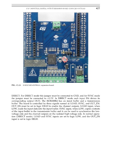
FIG. 17.21 X-NUCLEO-OUT01A1 expansion board.
DIRECT. For DIRECT mode this jumper must be connected to GND, and for SYNC mode
the jumper must be connected to +3.3V. In DIRECT mode each input INi drives its
corresponding output OUTi. The ISO8200BQ has an input buffer and a transmission
buffer. The board is controlled by three signals named as LOAD, SYNC, and OUT_EN.
OUT_EN must be set to logic HIGH to enable the channel outputs. LOAD input, when
LOW, loads the input data into the input buffer. SYNC input, when LOW, copies contents
of the input buffer to the transmission buffer and it can be used to synchronize the low-
voltage side and the channel outputs on the isolated high-voltage side. In normal opera-
tion (DIRECT mode), LOAD and SYNC inputs are set to logic LOW, and the OUT_EN
input is set to logic HIGH.