
Page 444 - ARM Based Microcontroller Projects Using MBED
P. 444
430 17. STM32 NUCLEO EXPANSION BOARDS
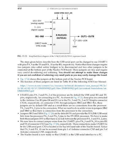
FIG. 17.23 Simplified block diagram of the X-NUCLEO-OUT01A1 expansion board.
The steps given below describe how the USB serial port can be changed to use USART 1
with pins PA_9 as the TX and PA_10 as the RX, respectively. Notice that these changes require
two jumpers (also called solder bridges) to be disconnected and two other jumpers to be
connected at the bottom part of the Nucleo PCB board. These jumpers are tiny and require
very careful de-soldering and soldering. You should not attempt to make these changes
if you are not confident of soldering very small parts as you may easily damage the board:
• Fig. 17.24 shows the jumpers at the bottom part of the Nucleo PCB board.
• The function of these jumpers are listed in Table 10 of the following STM User Manual:
https://www.st.com/content/ccc/resource/technical/document/user_manual/98/2e/
fa/4b/e0/82/43/b7/DM00105823.pdf/files/DM00105823.pdf/jcr:content/translations/en.
DM00105823.pdf
• USART2 pins PA_3 and PA_2 of the processor are by default the USB serial RX and TX
pins, respectively, for connecting to a PC. As shown in Fig. 17.25, these pins are connected
to the Arduino Uno R3 pins D0 and D1 (or to the PA_3 and PA_2 on ST Morpho connector
CN10), respectively, on connector CN9, through jumpers SB62 and SB63. But, these
jumpers are by default OFF and as a result there are no connections from the processor
PA_3 and PA_2 pins to the connectors. What we need to do is solder wires to jumpers SB62
and SB63 so that there is connection from the processor to the connectors.
• Jumpers SB13 and SB14 (Fig. 17.26) are by default ON and provide the ST-LINK USB serial
link from the processor PA_3 and PA_2 pins to the ST-LINK processor. We have to make
both these jumpers OFF so that there is no link between the processor PA_3 and PA_2 pins.
• We now have to connect jumper wires from the USART1 pins PA_9 and PA_10 to pins RX
and TX of connector CN3 (see Fig. 17.26), respectively. These connections make USART1 to
be the USB serial port. CN3 is located at the top left-hand side of the Nucleo board. Notice
that PA_9 and PA_10 can be accessed from pin 1 of Arduino connector CN5 and pin 3 of
Arduino connector CN9, respectively.
• The Nucleo board is now ready so that USART1 is the USB serial interface to a PC.