
Page 446 - ARM Based Microcontroller Projects Using MBED
P. 446
432 17. STM32 NUCLEO EXPANSION BOARDS
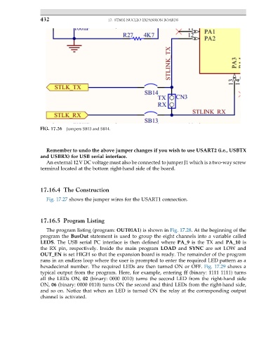
FIG. 17.26 Jumpers SB13 and SB14.
Remember to undo the above jumper changes if you wish to use USART2 (i.e., USBTX
and USBRX) for USB serial interface.
An external 12V DC voltage must also be connected to jumper J1 which is a two-way screw
terminal located at the bottom right-hand side of the board.
17.16.4 The Construction
Fig. 17.27 shows the jumper wires for the USART1 connection.
17.16.5 Program Listing
The program listing (program: OUT01A1) is shown in Fig. 17.28. At the beginning of the
program the BusOut statement is used to group the eight channels into a variable called
LEDS. The USB serial PC interface is then defined where PA_9 is the TX and PA_10 is
the RX pin, respectively. Inside the main program LOAD and SYNC are set LOW and
OUT_EN is set HIGH so that the expansion board is ready. The remainder of the program
runs in an endless loop where the user is prompted to enter the required LED pattern as a
hexadecimal number. The required LEDs are then turned ON or OFF. Fig. 17.29 shows a
typical output from the program. Here, for example, entering ff (binary: 1111 1111) turns
all the LEDs ON, 02 (binary: 0000 0010) turns the second LED from the right-hand side
ON, 06 (binary: 0000 0110) turns ON the second and third LEDs from the right-hand side,
and so on. Notice that when an LED is turned ON the relay at the corresponding output
channel is activated.