Page 442 - ARM Based Microcontroller Projects Using MBED
P. 442
428                        17. STM32 NUCLEO EXPANSION BOARDS

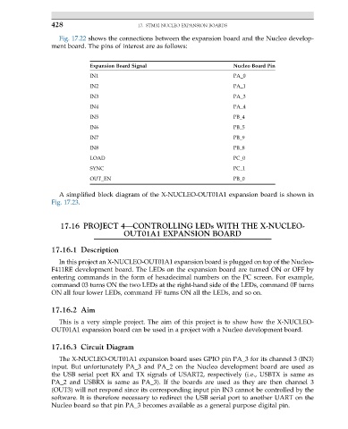
                   Fig. 17.22 shows the connections between the expansion board and the Nucleo develop-
                 ment board. The pins of interest are as follows:


                             Expansion Board Signal                      Nucleo Board Pin
                             IN1                                         PA_0
                             IN2                                         PA_1
                             IN3                                         PA_3
                             IN4                                         PA_4
                             IN5                                         PB_4
                             IN6                                         PB_5
                             IN7                                         PB_9
                             IN8                                         PB_8
                             LOAD                                        PC_0
                             SYNC                                        PC_1
                             OUT_EN                                      PB_0

                   A simplified block diagram of the X-NUCLEO-OUT01A1 expansion board is shown in
                 Fig. 17.23.


                    17.16 PROJECT 4—CONTROLLING LEDs WITH THE X-NUCLEO-
                                       OUT01A1 EXPANSION BOARD


                 17.16.1 Description
                   In this project an X-NUCLEO-OUT01A1 expansion board is plugged on top of the Nucleo-
                 F411RE development board. The LEDs on the expansion board are turned ON or OFF by
                 entering commands in the form of hexadecimal numbers on the PC screen. For example,
                 command 03 turns ON the two LEDs at the right-hand side of the LEDs, command 0F turns
                 ON all four lower LEDs, command FF turns ON all the LEDs, and so on.

                 17.16.2 Aim

                   This is a very simple project. The aim of this project is to show how the X-NUCLEO-
                 OUT01A1 expansion board can be used in a project with a Nucleo development board.

                 17.16.3 Circuit Diagram

                   The X-NUCLEO-OUT01A1 expansion board uses GPIO pin PA_3 for its channel 3 (IN3)
                 input. But unfortunately PA_3 and PA_2 on the Nucleo development board are used as
                 the USB serial port RX and TX signals of USART2, respectively (i.e., USBTX is same as
                 PA_2 and USBRX is same as PA_3). If the boards are used as they are then channel 3
                 (OUT3) will not respond since its corresponding input pin IN3 cannot be controlled by the
                 software. It is therefore necessary to redirect the USB serial port to another UART on the
                 Nucleo board so that pin PA_3 becomes available as a general purpose digital pin.

