
Page 127 - Acquisition and Processing of Marine Seismic Data
P. 127
118 2. MARINE SEISMIC DATA ACQUISITION
Depth of the streamer(s) should be controlled 2.5.1.3 Group Interval
carefully, especially for high-resolution surveys Group interval is the distance between the cen-
where the streamer is towed at relatively shal- ters of two adjacent recording channels. In marine
low depths. In high-salinity warmer waters, seismic equipment, the group interval isdesigned
streamer trimming with specific weights may during production and cannot be modified later
be necessary. If some sections of the streamer except that it can be increased by trace summing
are shallower than the remaining sections, then option provided by digital seismic streamers.
the channels in shallow sections record too Since a smaller interval provides a smaller inline
much swell noise. If they are deeper, however, binsize(whichalwaysequalsthehalfgroupinter-
this results in distinct phase distortions along val, as shown in Fig. 2.72), and hence better inline
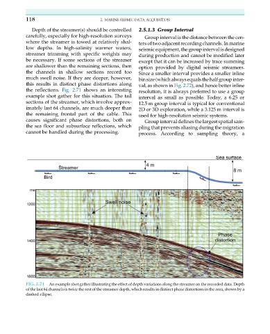
the reflections. Fig. 2.71 shows an interesting resolution, it is always preferred to use a group
example shot gather for this situation. The tail interval as small as possible. Today, a 6.25 or
sections of the streamer, which involve approx- 12.5 m group interval is typical for conventional
imately last 64 channels, are much deeper than 2D or 3D exploration, while a 3.125 m interval is
the remaining frontal part of the cable. This used for high-resolution seismic systems.
causes significant phase distortions, both on Group interval defines the largest spatial sam-
the sea floor and subsurface reflections, which pling that prevents aliasing during the migration
cannot be handled during the processing. process. According to sampling theory, a
FIG. 2.71 An example shot gather illustrating the effect of depth variations along the streamer on the recorded data. Depth
of the last 64 channels is twice the rest of the streamer depth, which results in distinct phase distortions in the area, shown by a
dashed ellipse.