
Page 124 - Acquisition and Processing of Marine Seismic Data
P. 124
2.5 DATA ACQUISITION PARAMETERS 115
every shot point whenever the vessel reaches a a careful analyzing of the vintage seismic data.
shot location. On time break at a shot point, Then the minimum shot interval which is larger
recording immediately starts and continues than the recording length is calculated so that it is
until the last time sample of the record length an exact multiple of group interval (for instance,
is received and recorded. The key parameter shot interval can be 12.5, 25, 37.5 m, etc., for a
here is the time period that the vessel travels 12.5 m group interval).
between two consecutive shot points. This time Shot interval directly affects the optimum
period should exceed the recording length; oth- fold of the data: The smaller the shot interval,
erwise the vessel reaches the next shot location the higher the optimum fold, and hence, the
before the recording of the previous shot is com- higher the S/N ratio of the seismic data. There-
pleted. This situation is termed overlapped shot fore, it is always preferable to shot at regular
points, in which the time between two consecu- intervals as small as possible. In practice, a safe
tive shot points is less than the record length, time is set between the end of recording of the
which appears whenever the vessel speed is previous shot and the time of the forthcoming
too fast during the acquisition. shot. That is, the vessel should arrive to the next
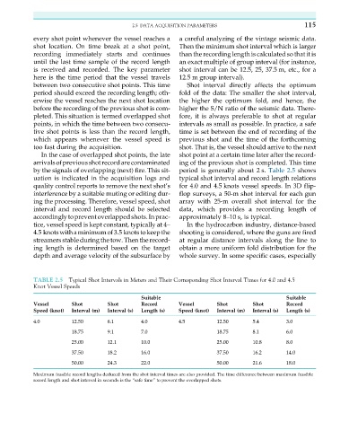
In the case of overlapped shot points, the late shot point at a certain time later after the record-
arrivalsofpreviousshotrecordarecontaminated ing of the previous shot is completed. This time
by the signals of overlapping (next) fire. This sit- period is generally about 2 s. Table 2.5 shows
uation is indicated in the acquisition logs and typical shot interval and record length relations
quality control reports to remove the next shot’s for 4.0 and 4.5 knots vessel speeds. In 3D flip-
interference by a suitable muting or editing dur- flop surveys, a 50-m shot interval for each gun
ing the processing. Therefore, vessel speed, shot array with 25-m overall shot interval for the
interval and record length should be selected data, which provides a recording length of
accordinglytopreventoverlappedshots.Inprac- approximately 8–10 s, is typical.
tice, vessel speed is kept constant, typically at 4– In the hydrocarbon industry, distance-based
4.5 knotswithaminimumof3.5 knotstokeepthe shooting is considered, where the guns are fired
streamersstable during the tow. Then the record- at regular distance intervals along the line to
ing length is determined based on the target obtain a more uniform fold distribution for the
depth and average velocity of the subsurface by whole survey. In some specific cases, especially
TABLE 2.5 Typical Shot Intervals in Meters and Their Corresponding Shot Interval Times for 4.0 and 4.5
Knot Vessel Speeds
Suitable Suitable
Vessel Shot Shot Record Vessel Shot Shot Record
Speed (knot) Interval (m) Interval (s) Length (s) Speed (knot) Interval (m) Interval (s) Length (s)
4.0 12.50 6.1 4.0 4.5 12.50 5.4 3.0
18.75 9.1 7.0 18.75 8.1 6.0
25.00 12.1 10.0 25.00 10.8 8.0
37.50 18.2 16.0 37.50 16.2 14.0
50.00 24.3 22.0 50.00 21.6 18.0
Maximum feasible record lengths deduced from the shot interval times are also provided. The time difference between maximum feasible
record length and shot interval in seconds is the “safe time” to prevent the overlapped shots.