
Page 119 - Acquisition and Processing of Marine Seismic Data
P. 119
110 2. MARINE SEISMIC DATA ACQUISITION
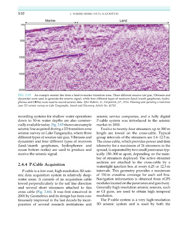
FIG. 2.65 An example seismic line from a land-to-marine transition zone. Three different sources (air gun, Vibroseis and
dynamite) were used to generate the seismic signal, while four different types of receivers (land/marsh geophones, hydro-
phones and OBNs) were used to record seismic data. After Roberts, D., Fitzpatrick, J.P., 2016. Planning and operating a transition
zone 2D seismic survey on Lake Tanganyika, Search and Discovery Article No. 41765.
recording systems for shallow water operations seismic service companies, and a fully digital
down to 50-m water depths are also commer- P-cable system was introduced to the seismic
ciallyavailabletoday.Fig.2.65showsanexample market in 2010.
seismic line acquired during a 2D transition zone Twelve to twenty-four streamers up to 300 m
seismic survey on Lake Tanganyika, where three length are towed on the cross-cable. Typical
different types of sources (air gun, Vibroseis and group intervals of the streamers are 1.6–12.5 m.
dynamite) and four different types of receivers The cross-cable, which provides power and data
(land/marsh geophones, hydrophones and telemetry for a maximum of 24 streamers in the
ocean bottom nodes) are used to produce and spread, is separated by two small paravanes typ-
receive the seismic signal. ically 150–300 m apart, depending on the num-
ber of streamers deployed. The active streamer
sections are attached to the cross-cable by a
2.4.4 P-Cable Acquisition
watertight junction box at every 6.25 or 12.5 m
P-cable is a low-cost, high-resolution 3D seis- intervals. This geometry provides a maximum
mic data acquisition system in relatively deep- of 150 m crossline coverage for each sail line.
water areas. It consists of an acquisition cable Navigation information is obtained from rGPS
towed perpendicularly to the sail line direction modules located on the paravanes and gun buoy.
and several short streamers attached to this Generally high-resolution seismic sources, such
cross cable (Fig. 2.66). It was first conceived in as GI guns, are used to obtain high temporal
2001 by Geometrics and its design has been con- resolution.
tinuously improved in the last decade by incor- The P-cable system is a very high-resolution
poration of several research institutions and 3D seismic system and is used by both the