
Page 128 - Acquisition and Processing of Marine Seismic Data
P. 128
2.5 DATA ACQUISITION PARAMETERS 119
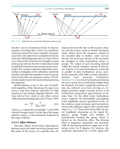
FIG. 2.72 Inline bin size equals the half group interval (Δx).
function can be reconstructed from its discrete distance between the first (or the nearest) chan-
samples, providing that at least two amplitude nel and the source center is termed minimum
values per period have been sampled. In seismic offset, which affects the frequency content of
acquisition, the subsurface is sampled at discrete the recorded data in shallow water surveys
intervals of the half group interval, which allows because the receiving channels of the streamers
us to retrieve the minimum wavelength as equal are designed to form hydrophone arrays or
to the group interval. In other words, data should groups. The output of each recording channel
bespatiallysampledatleasttwopointsperwave- within the seismic streamer consists of individ-
length. For a proper migration application, hori- ual outputs of several hydrophones connected
zontal wavelengths of the reflections should be in parallel to form hydrophone arrays, posi-
suitably and regularly sampled so that the group tioned along the cable with a certain separation
interval provides an adequate number of hori- between each particular hydrophone
zontal samples to prevent spatial aliasing during (Section 2.1.2). As a result, hydrophones forming
the migration. the array spread the overall group length along
Spatial aliasing occurs in the case of insuffi- the streamer. For such a composite receiver sys-
cient sampling of the data along the space axis tem, the reflected wave front arriving at a 0-
using a large trace interval, especially for high degree incidence angle (vertical) arrives at all
frequencies and steeply dipping reflectors. The hydrophone components approximately at the
trace interval for a stack or zero offset section same time. On the other hand, hydrophone
withoutspatialaliasingisgivenby(Yılmaz,1987) arrays suppress the horizontally propagating
noise amplitudes such as operational noise. As
V
λ app
Δx ¼ (2.2) the incidence angle increases, each hydrophone
2 4f max sinθ
receives the reflection signal with a certain time
where λ app is apparent wavelength, V is the RMS delay (Fig. 2.73). These time delays filter the sig-
velocity at target depth, θ is the dip of the target nal amplitude depending on the signal fre-
reflector, and f max is the maximum frequency at quency, group length and number of
the target reflector. hydrophones forming the group, which is
known as the directivity effect. The filtering
2.5.1.4 Offset Distance effect is frequency dependent and decreases
The term “offset” of each trace is the distance with the decreasing incidence angle and no fil-
between each individual recording channel and tering occurs for 0 degrees. For instance, the
the center of the source. As a specific case, the amplitude attenuation for a 50-Hz signal with