
Page 241 - Acquisition and Processing of Marine Seismic Data
P. 241
232 4. FUNDAMENTALS OF DATA PROCESSING
1 wave fields, can be decomposed into plane wave
utðÞ ¼ xtðÞ + i *xtðÞ
1 achieved by applying a linear time shift to the
πt (4.33) components. This decomposition process is
utðÞ ¼ δ tðÞ + i *xtðÞ
πt data and then summing the amplitudes along
the offset axis.
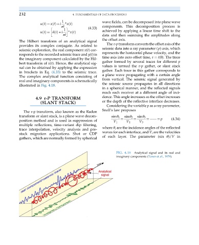
The Hilbert transform of an analytical signal
The τ-p transform converts the offset axis of the
provides its complex conjugate. As related to
seismic data into a ray parameter (p) axis, which
seismic exploration, the real component x(t) cor-
represents the horizontal phase velocity, and the
responds to the recorded seismic trace and y(t)is
time axis into zero offset time, τ ¼ t(0). The trace
the imaginary component calculated by the Hil-
gather formed by several traces for different p
bert transform of x(t). Hence, the analytical sig-
values is termed the τ-p gather, or slant stack
nal can be obtained by applying the expression
gather. Each trace in this gather corresponds to
in brackets in Eq. (4.33) to the seismic trace.
The complex analytical function consisting of a plane wave propagating with a certain angle
real and imaginary components is schematically from vertical. The seismic signal generated by
illustrated in Fig. 4.18. the seismic source propagates in all directions
in a spherical manner, and the reflected signals
reach each receiver at a different angle of inci-
4.9 τ-P TRANSFORM dence. This angle increases as the offset increases
(SLANT STACK) or the depth of the reflective interface decreases.
Considering the variable p as a ray parameter,
Snell’s law proposes
The τ-p transform, also known as the Radon
transform or slant stack, is a plane wave decom- sinθ 1 sinθ 2 sinθ 3
position method and is used in suppression of ¼ ¼ ¼ ⋯⋯ ¼ p (4.34)
V 1 V 2 V 3
multiple reflections, time-variant dip filtering,
trace interpolation, velocity analysis and pre- where θ i are the incidence angles of the reflected
stack migration applications. Shot or CDP waves for each interface, and V i are the velocities
gathers, which are normally formed by spherical of each layer. The parameter (sin θ)/V in
FIG. 4.18 Analytical signal and its real and
imaginary components (Taner et al., 1979).