
Page 264 - Acquisition and Processing of Marine Seismic Data
P. 264
5.5 BAND-PASS FILTER 255
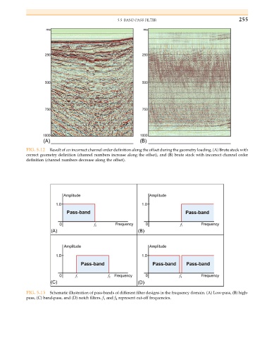
FIG. 5.12 Result of an incorrect channel order definition along the offset during the geometry loading. (A) Brute stack with
correct geometry definition (channel numbers increase along the offset), and (B) brute stack with incorrect channel order
definition (channel numbers decrease along the offset).
FIG. 5.13 Schematic illustration of pass-bands of different filter designs in the frequency domain. (A) Low-pass, (B) high-
pass, (C) band-pass, and (D) notch filters. f 1 and f 2 represent cut-off frequencies.