
Page 259 - Acquisition and Processing of Marine Seismic Data
P. 259
250 5. PREPROCESSING
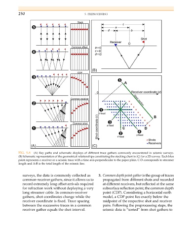
FIG. 5.8 (A) Ray paths and schematic displays of different trace gathers commonly encountered in seismic surveys.
(B) Schematic representation of the geometrical relationships constituting the stacking chart in (C) for a 2D survey. Each blue
point represents a receiver or a seismic trace with a time axis perpendicular to the paper plain. C-D corresponds to streamer
length and A-B is the total length of the seismic line.
surveys, the data is commonly collected as 3. Common depth point gather is the group of traces
common-receiver gathers, since it allows us to propagated from different shots and recorded
record extremely long offset arrivals required at different receivers, but reflected at the same
for refraction work without deploying a very subsurface reflection point, the common depth
long streamer cable. In common-receiver point (CDP). Considering a horizontal earth
gathers, shot coordinates change while the model, a CDP point lies exactly below the
receiver coordinate is fixed. Trace spacing midpoint of the respective shot and receiver
between the successive traces in a common pairs. Following the preprocessing steps, the
receiver gather equals the shot interval. seismic data is “sorted” from shot gathers to