
Page 255 - Acquisition and Processing of Marine Seismic Data
P. 255
246 5. PREPROCESSING
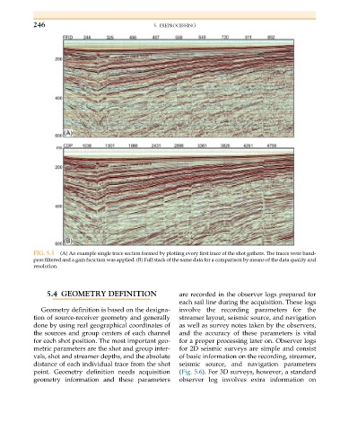
FIG. 5.5 (A) An example single trace section formed by plotting every first trace of the shot gathers. The traces were band-
pass filtered and a gain function was applied. (B) Full stack of the same data for a comparison by means of the data quality and
resolution.
5.4 GEOMETRY DEFINITION are recorded in the observer logs prepared for
each sail line during the acquisition. These logs
Geometry definition is based on the designa- involve the recording parameters for the
tion of source-receiver geometry and generally streamer layout, seismic source, and navigation
done by using real geographical coordinates of as well as survey notes taken by the observers,
the sources and group centers of each channel and the accuracy of these parameters is vital
for each shot position. The most important geo- for a proper processing later on. Observer logs
metric parameters are the shot and group inter- for 2D seismic surveys are simple and consist
vals, shot and streamer depths, and the absolute of basic information on the recording, streamer,
distance of each individual trace from the shot seismic source, and navigation parameters
point. Geometry definition needs acquisition (Fig. 5.6). For 3D surveys, however, a standard
geometry information and these parameters observer log involves extra information on