
Page 253 - Acquisition and Processing of Marine Seismic Data
P. 253
244 5. PREPROCESSING
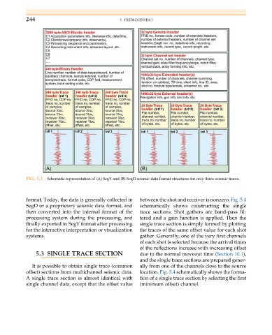
FIG. 5.3 Schematic representation of (A) SegY and (B) SegD seismic data format structures for only three seismic traces.
format. Today, the data is generally collected in between the shot and receiver is nonzero. Fig. 5.4
SegD or a proprietary seismic data format, and schematically shows constructing the single
then converted into the internal format of the trace sections: Shot gathers are band-pass fil-
processing system during the processing, and tered and a gain function is applied. Then the
finally exported in SegY format after processing single trace section is simply formed by plotting
for the interactive interpretation or visualization the traces of the same offset value for each shot
systems. gather. Generally, one of the very first channels
of each shot is selected because the arrival times
of the reflections increase with increasing offset
5.3 SINGLE TRACE SECTION due to the normal moveout time (Section 10.1),
and the single trace sections are prepared gener-
It is possible to obtain single trace (common ally from one of the channels close to the source
offset) sections from multichannel seismic data. location. Fig. 5.4 schematically shows the forma-
A single trace section is almost identical with tion of a single trace section by selecting the first
single channel data, except that the offset value (minimum offset) channel.