
Page 254 - Acquisition and Processing of Marine Seismic Data
P. 254
5.3 SINGLE TRACE SECTION 245
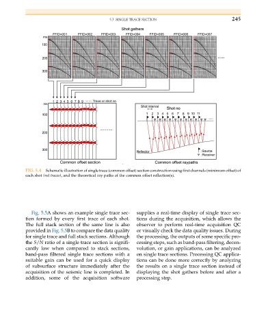
FIG. 5.4 Schematic illustration of single trace (common offset) section construction using first channels (minimum offset) of
each shot (red traces), and the theoretical ray paths of the common offset reflection(s).
Fig. 5.5A shows an example single trace sec- supplies a real-time display of single trace sec-
tion formed by every first trace of each shot. tions during the acquisition, which allows the
The full stack section of the same line is also observer to perform real-time acquisition QC
provided in Fig. 5.5B to compare the data quality or visually check the data quality issues. During
for single trace and full stack sections. Although the processing, the outputs of some specific pro-
the S/N ratio of a single trace section is signifi- cessing steps, such as band-pass filtering, decon-
cantly low when compared to stack sections, volution, or gain applications, can be analyzed
band-pass filtered single trace sections with a on single trace sections. Processing QC applica-
suitable gain can be used for a quick display tions can be done more correctly by analyzing
of subsurface structure immediately after the the results on a single trace section instead of
acquisition of the seismic line is completed. In displaying the shot gathers before and after a
addition, some of the acquisition software processing step.