
Page 256 - Acquisition and Processing of Marine Seismic Data
P. 256
5.4 GEOMETRY DEFINITION 247
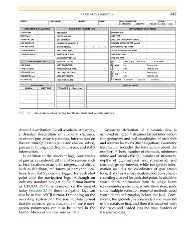
FIG. 5.6 An example observer log for 2D multichannel seismic surveys.
channel distribution for all available streamers, Geometry definition of a seismic line is
a detailed description of auxiliary channels, achieved using both streamer layout information
streamer/gun array separation, information on (the geometry)and real coordinatesofeachshot
the real-time QC results (shot and channel edits), and receiver locations (the navigation). Geometry
gun array timing and drop out issues, and rGPS information includes the information about the
information. number of shots, number of channels, minimum
In addition to the observer logs, coordinates inline and lateral offset(s), number of streamers,
of gun array center(s), all available sensors such depths of gun array(s) and streamer(s), and
as bird locations or acoustic rangers, and offsets streamer group interval, while navigation infor-
such as dilt floats, tail buoys or paravane loca- mation includes the coordinates of gun arrays
tions from rGPS pods are logged for each shot for each shot as well ascalculated locations of each
point into the navigation logs. Although an recording channel for each shot point. In addition,
industry standard navigation file format known water depth information from the single beam
as UKOOA P1/90 is common on the market echo-sounder is also entered into the system, since
today (Section 2.1.7), these navigation logs can some multiple reflection removal methods need
also be in free ASCII format. Depending on the water depth information below the keel. Com-
recording system and the seismic data format monly, the geometry is constructed and recorded
that the recorder generates, some of these navi- in the database first, and then it is matched with
gation parameters can also be stored in the the traces and loaded into the trace headers of
header blocks of the raw seismic data. the seismic data.