
Page 268 - Acquisition and Processing of Marine Seismic Data
P. 268
5.5 BAND-PASS FILTER 259
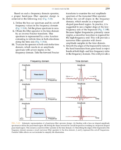
Based on such a frequency domain operator, transform to examine the real amplitude
a proper band-pass filter operator design is spectrum of the truncated filter operator.
achieved in the following way (Fig. 5.18): iv. Define the cut-off slopes in the frequency
domain, which results in a trapezoid
i. Define the box-car spectrum and its cut-off shaped pass-band region. In practice, it is
frequency values in the frequency domain
suggested to use a higher slope at the low-
(Fig. 5.18A). Set the phase spectrum to zero.
frequency side of the trapezoid (Fig. 5.18B).
ii. Obtain the filter operator in the time domain
Because higher frequencies primarily cause
by an inverse Fourier transform. This
ripples, a smoother transition is required for
spectrum is represented by a sinc function
the high-frequency end. This will provide a
extending to infinite time in both directions
narrower filter operator with fewer
along the time axis (Fig. 5.18A).
amplitude samples in the time domain.
iii. Truncate the operator at both ends in the time
v. Smooth the edges of the trapezoid to remove
domain, which results in an amplitude
the hard transition from pass-band to reject
spectrum with severe ripples in the
bands at both high- and low-frequency sides
frequency domain. Take the forward Fourier
in the frequency domain. This will provide a
FIG. 5.18 Schematic representation of a band-pass filter operator design. (A) Starting with a box-car shaped amplitude
spectrum to define the pass-band region. (B) Setting the slopes around the cut-off frequencies resulting in a trapezoid shaped
pass-band region. This ensures a narrower filter operator in the time domain. (C) Smoothing the edges of the trapezoid in the
frequency domain ensures a much narrower filter operator in the time domain. f 1 and f 2 represent the cut-off frequencies.
Possible Gibbs effects are not included to simplify the illustration.