
Page 403 - Acquisition and Processing of Marine Seismic Data
P. 403
394 7. SUPPRESSION OF MULTIPLE REFLECTIONS
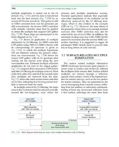
multiple amplitudes is muted out in the f-k primary and multiple amplitudes overlap.
domain (Fig. 7.27C) and the data is transferred Practical applications indicate that especially
back into the time domain (Fig. 7.27D) by an near-offset amplitudes of the multiples can be
inverse 2D Fourier transform. This gather is still effectively removed by the f-k filtering tech-
in NMO corrected form and the primaries are nique, which is also evident in the example
still overcorrected. An inverse NMO correction CDPs in Fig. 7.30. However, the near offsets of
with multiple velocities must then be applied the primaries where there is no enough residual
to obtain the multiple free original CDP gather moveout after NMO correction may also be
(Fig. 7.27E). These steps are summarized in the removed by use of an f-k filter. In addition, the
block diagram in Fig. 7.28. automatic muting zone due to the NMO stretch
Fig. 7.29 shows an application of multiple cannot be recovered after the inverse NMO cor-
elimination by f-k filtering. An NMO corrected rection; therefore, it is suggested to toggle off
CDP gather using 1500 m/s NMO velocity with automated NMO stretch mute to prevent data
its corresponding f-k spectrum is given in loss in long offsets of early arrivals.
Fig. 7.29A, in which the multiple hyperbolas
(M) are flattened whereas the primary reflec-
tions are overcorrected. Fig. 7.29B shows the 7.7 SURFACE-RELATED MULTIPLE
output CDP gather with its f-k spectrum after ELIMINATION
muting out the narrow zone along the zero
wavenumber axis. Flattened multiple reflection The surface related multiple elimination
amplitudes do not exist in the output gather. (SRME) technique has become quite popular in
Fig. 7.30 compares three successive CDPs before recent years to predict and iteratively subtract
and after f-k filtering for multiple removal. Most the multiples from seismic data. Surface-related
of the first-order (M 1 ) and all of the second-order multiples are formed through a reflection
(M 2 ) multiples are removed from the data. against a free surface, which is the topmost sur-
Fig. 7.31 shows the stack section before and after face for seismic surveys, such as the sea surface
an f-k filter, indicating that the long period mul- for marine seismics. They are generated by the
tiple is removed from the stack. waves downgoing from a seismic source, reflec-
In multiple removal by f-k filtering, the mute ting from the seafloor or subsurface sediments,
zone in the f-k domain must be selected carefully having at least one downward reflection from
around the low-frequency zone where the a free surface, reflecting one more time from
FIG. 7.28 Block diagram illustrating the steps of the multiple elimination with f-k filtering.