
Page 465 - Acquisition and Processing of Marine Seismic Data
P. 465
456 9. VELOCITY ANALYSIS
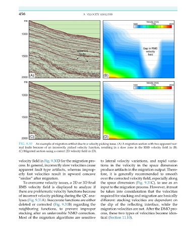
FIG. 9.30 An example of migration artifact due to a velocity picking issue. (A) A migration section with two apparent nor-
mal faults because of an incorrectly picked velocity function, resulting in a slow zone in the RMS velocity field in (B).
(C) Migrated section using a correct 2D velocity field in (D).
velocity field in Fig. 9.30D for the migration pro- to lateral velocity variations, and rapid varia-
cess. In general, incorrectly slow velocities cause tions in the velocity in the space dimension
apparent fault type artifacts, whereas improp- produce artifacts in the migration output. There-
erly fast velocities result in upward concave fore, it is generally recommended to smooth
“smiles” after migration. over the corrected velocity field, especially along
To overcome velocity issues, a 2D or 3D final the space dimension (Fig. 9.31C), to use as an
RMS velocity field is displayed to analyze if input to the migration process. However, it must
there are problematic velocity functions because be taken into consideration that the velocities
of incorrect velocity picking during the QC ana- required for stacking and migration are basically
lyses (Fig. 9.31A). Inaccurate functions are either different: stacking velocities are dependent on
deleted or corrected (Fig. 9.31B) regarding the the dip of the reflecting interface, while the
neighboring functions, to prevent improper migration velocities are not. After the DMO pro-
stacking after an unfavorable NMO correction. cess, these two types of velocities become iden-
Most of the migration algorithms are sensitive tical (Section 11.10).