
Page 504 - Acquisition and Processing of Marine Seismic Data
P. 504
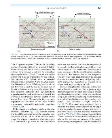
11.1 MIGRATION CONCEPT                           495


           FIG. 11.1  (A) Zero-offset reflections from an interface between points C and D in the subsurface are recorded between
           surface locations A and B. (B) These reflections appear on the seismic section between points C and D’ directly beneath
                                                                                 0
           the surface locations A and B, and are moved to their correct subsurface locations C and D by migration.
           Point C appears at point C below the recording  reflectors, the seismic line must be long enough
                                   0
           location A, and point D occurs at point D’ below  to consider the lateral displacement of the events
           the recording location B. As a consequence, the  after migration. The amount of lateral displace-
           reflector lying between C and D in the subsurface  ment increases with the recording time and is a
           shows up between C and D’ on the zero-offset  function of the square root of the migration
                              0
           section and must be migrated to its true subsur-  velocity. The extra area that must be covered
           face location C-D. Seismic data is recorded  due to the lateral movement of dipping reflec-
           between surface locations A and B. After migra-  tions during the migration is referred to as
           tion, however, reflector C-D is migrated to a loca-  migration fringe, or migration halo.
           tion between O and A, that is, an area out of   In order to replace the reflections to their cor-
           the zero-offset recording zone (the seismic line).  rect subsurface positions, the migration algo-
           This situation indicates that the reflections  rithm swings arcs for each time sample of each
           appearing on the stack sections are not restricted  trace based on the velocity of the processed time
           to involve the structures directly located on the  sample, in order to determine possible locations
           seismic line plane. The opposite is even more  from which a reflection event has possibly orig-
           important: the structure on the stack section  inated. Let’s consider a single arrival in
           may no longer exist on the section after migration  Fig. 11.2A. This event may originate from a
           (Yılmaz, 2001).                              reflector positioned at any location on an ellipse
              If the target is a reflector, such as the one  in the subsurface between source and receiver
           between C and D in Fig. 11.1A, then the seismic  positions, such as the ones indicated by numbers
           line should be extended along the recording sur-  from I to IV in Fig. 11.2B as example possibilities.
           face from A-B to O-B in order to successfully  To find out which location is the correct one, we
           image the dipping structures after migration.  rely on the interference process of the ampli-
           If a structural dip exists in the subsurface  tudes during the migration over the amplitudes