
Page 505 - Acquisition and Processing of Marine Seismic Data
P. 505
496 11. SEISMIC MIGRATION
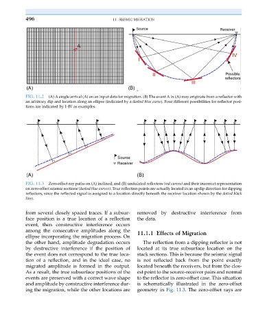
FIG. 11.2 (A) A single arrival (A) on an input data for migration. (B) The event A in (A) may originate from a reflector with
an arbitrary dip and location along an ellipse (indicated by a dashed blue curve). Four different possibilities for reflector posi-
tions are indicated by I–IV as examples.
FIG. 11.3 Zero-offset ray paths on (A) inclined, and (B) undulated reflectors (red curves) and their incorrect representation
on zero-offset seismic sections (dashed blue curves). True reflection points are actually located in an updip direction for dipping
reflectors, since the reflected signal is assigned to a location directly beneath the receiver location shown by the dotted black
lines.
from several closely spaced traces. If a subsur- removed by destructive interference from
face position is a true location of a reflection the data.
event, then constructive interference occurs
among the consecutive amplitudes along the 11.1.1 Effects of Migration
ellipse incorporating the migration process. On
the other hand, amplitude degradation occurs The reflection from a dipping reflector is not
by destructive interference if the position of located at its true subsurface location on the
the event does not correspond to the true loca- stack sections. This is because the seismic signal
tion of a reflection, and in the ideal case, no is not reflected back from the point exactly
migrated amplitude is formed in the output. located beneath the receivers, but from the clos-
As a result, the true subsurface positions of the est point to the source-receiver pairs and normal
events are preserved with a correct wave shape to the reflector in zero-offset case. This situation
and amplitude by constructive interference dur- is schematically illustrated in the zero-offset
ing the migration, while the other locations are geometry in Fig. 11.3. The zero-offset rays are