
Page 506 - Acquisition and Processing of Marine Seismic Data
P. 506
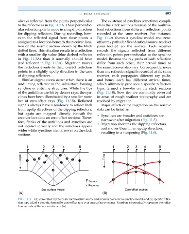
11.1 MIGRATION CONCEPT                           497

           always reflected from the points perpendicular  The existence of synclines sometimes compli-
           to the reflector as in Fig. 11.3A. These perpendic-  cates the stack sections because of the multiva-
           ular reflection points move in an updip direction  lued reflections from different reflection points
           for dipping reflectors. During recording, how-  recorded at the same receiver. For instance,
           ever, the reflected signal from these points is  Fig. 11.4A shows a syncline model and zero-
           assigned to a location beneath the receiver loca-  offset ray paths for five identical source-receiver
           tion on the seismic section shown by the black  pairs located on the surface. Each receiver
           dotted lines. This situation results in a reflection  records the signals reflected from different
           with a smaller dip value (blue dashed reflector  reflection points perpendicular to the syncline
           in Fig. 11.3A) than it normally should have  model. Because the ray paths of each reflection
           (red reflector in Fig. 11.3A). Migration moves  differ from each other, their arrival times to
           the reflection events to their correct reflection  the same receiver also vary. Consequently, more
           points in a slightly updip direction in the case  than one reflection signal is recorded at the same
           of dipping reflectors.                       receiver, each propagates different ray paths,
              Similar degradations occur when there is an  and hence each has different arrival times,
           undulating reflector in the subsurface forming  which ultimately produces a specific reflection
           syncline or anticline structures. While the tips  type, termed a bow-tie on the stack sections
           of the anticlines are hit by denser rays, the syn-  (Fig. 11.4B). Bow ties are commonly observed
           clines have been illuminated by a smaller num-  in areas of rough seafloor topography and are
           ber of zero-offset rays (Fig. 11.3B). Reflected  resolved by migration.
           signals always have a tendency to reflect back  Major effects of the migration on the seismic
           from updip directions of the dipping reflectors,  data can be listed as
           but again are mapped directly beneath the
           receiver locations on zero-offset sections. There-  • Synclines are broader and anticlines are
                                                           narrower after migration (Fig. 11.5).
           fore, flanks of the anticlines and synclines are  • Migration shortens the dipping reflectors,
           not located correctly and the anticlines appear  and moves them in an updip direction,
           wider while synclines are narrower on the stack  resulting in a steepening (Fig. 11.6).
           sections.


           FIG. 11.4  (A) Zero-offset ray paths for identical five source and receiver pairs over a syncline model, and (B) specific reflec-
           tion type called a bow-tie, formed by zero-offset rays over subsurface synclines. Numbers schematically represent the reflec-
           tion arrivals of the ray numbers in (A).