
Page 120 - Adaptive Identification and Control of Uncertain Systems with Nonsmooth Dynamics
P. 120
Dead-Zone Dynamics and Modeling 115
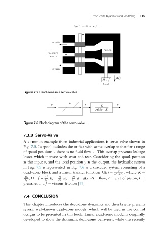
Figure 7.5 Dead-zone in a servo-valve.
Figure 7.6 Block diagram of the servo-valve.
7.3.3 Servo-Valve
A common example from industrial applications is servo-valve shown in
Fig. 7.5. Its spool occludes the orifice with some overlap so that for a range
of spool positions v there is no fluid flow u. This overlap prevents leakage
losses which increase with wear and tear. Considering the spool position
as the input v, and the load position y as the output, the hydraulic system
in Fig. 7.5 is represented in Fig. 7.6 as a cascaded system consisting of a
K
dead-zone block and a linear transfer function G(s) = ,where K =
2
Ms +Bs
Ak x A 2 ∂g ∂g
,B = f + ,k x = ,k p = ,g = g(x,P) = flow,A = area of piston,P =
k p k p ∂x ∂P
pressure, and f = viscous friction [11].
7.4 CONCLUSION
This chapter introduces the dead-zone dynamics and then briefly presents
several well-known dead-zone models, which will be used in the control
designs to be presented in this book. Linear dead-zone model is originally
developed to show the dominant dead-zone behaviors, while the recently