
Page 240 - Advanced Design Examples of Seismic Retrofit of Structures
P. 240
Example of a Steel Frame Building With Masonry Infill Walls Chapter 4 233
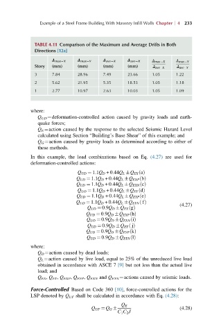
TABLE 4.11 Comparison of the Maximum and Average Drifts in Both
Directions [12a]
Δ max2X Δ max2Y Δ ave2X Δ ave2X Δ max X Δ max Y
Story (mm) (mm) (mm) (mm) Δ ave X Δ ave Y
3 7.84 28.96 7.49 23.66 1.05 1.22
2 5.62 21.95 5.35 18.53 1.05 1.18
1 2.77 10.97 2.63 10.03 1.05 1.09
where:
Q UD ¼deformation-controlled action caused by gravity loads and earth-
quake forces;
Q E ¼action caused by the response to the selected Seismic Hazard Level
calculated using Section “Building’s Base Shear” of this example; and
Q G ¼action caused by gravity loads as determined according to either of
these methods.
In this example, the load combinations based on Eq. (4.27) are used for
deformation-controlled actions:
Q UD ¼ 1:1Q D +0:44Q L Q EX aðÞ
Q UD ¼ 1:1Q D +0:44Q L Q EXP bðÞ
Q UD ¼ 1:1Q D +0:44Q L Q EXN cðÞ
Q UD ¼ 1:1Q D +0:44Q L Q EY dðÞ
Q UD ¼ 1:1Q D +0:44Q L Q EYP eðÞ
Q UD ¼ 1:1Q D +0:44Q L Q EYN fðÞ
(4.27)
Q UD ¼ 0:9Q D Q EX gðÞ
Q UD ¼ 0:9Q D Q EXP hðÞ
Q UD ¼ 0:9Q D Q EXN iðÞ
Q UD ¼ 0:9Q D Q EY jðÞ
Q UD ¼ 0:9Q D Q EYP kðÞ
Q UD ¼ 0:9Q D Q EYN lðÞ
where:
Q D ¼action caused by dead loads;
Q L ¼action caused by live load, equal to 25% of the unreduced live load
obtained in accordance with ASCE 7 [9] but not less than the actual live
load; and
Q EX , Q EY , Q EXP , Q EYP , Q EXN and Q EYN ¼actions caused by seismic loads.
Force-Controlled Based on Code 360 [10], force-controlled actions for the
LSP denoted by Q UF shall be calculated in accordance with Eq. (4.28):
Q E
Q UF ¼ Q G (4.28)
C 1 C 2 J