
Page 242 - Advanced Design Examples of Seismic Retrofit of Structures
P. 242
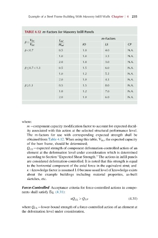
Example of a Steel Frame Building With Masonry Infill Walls Chapter  4 235


               TABLE 4.12 m-Factors for Masonry Infill Panels

                                                        m-Factors
                 V fre           L inf
               β ¼
                 V inf           H inf        IO          LS           CP
               β<0.7             0.5          1.0         4.0          N.A.
                                 1.0          1.0         3.5          N.A.
                                 2.0          1.0         3.0          N.A.
               β 0.7<1.3         0.5          1.5         6.0          N.A.
                                 1.0          1.2         5.2          N.A.
                                 2.0          1.0         4.5          N.A.
               β 1.3             0.5          1.5         8.0          N.A.
                                 1.0          1.2         7.0          N.A.
                                 2.0          1.0         6.0          N.A.


             where:
                m ¼component capacity modification factor to account for expected ductil-
                ity associated with this action at the selected structural performance level.
                The m-factors for use with corresponding expected strength shall be
                obtained from Table 4.12. When using this table, V fre , the expected capacity
                of the bare frame, should be determined;
                Q CE ¼expected strength of component deformation-controlled action of an
                element at the deformation level under consideration which is determined
                according to Section “Expected Shear Strength.” The actions in infill panels
                are considered deformation-controlled. It is noted that this strength is equal
                to the horizontal component of the axial force in the equivalent strut; and
                κ ¼knowledge factor is assumed 1.0 because usual level of knowledge exists
                about the example buildings including material properties, as-built
                sketches, etc.

             Force-Controlled Acceptance criteria for force-controlled actions in compo-
             nents shall satisfy Eq. (4.31):
                                        κQ CL  > Q UF                  (4.31)

             where Q CL ¼lower-bound strength of a force-controlled action of an element at
             the deformation level under consideration.