
Page 173 - Advanced Gas Turbine Cycles
P. 173
Chapter 8. Novel gas turbine cycles I39
from the last drum; carbon dioxide is collected from the other drums and compressed and
intercooled for final discharge.
Manfrida [4] argues that the heat demand and the substantial power loss associated with
‘presssure-swing’ physical absorption makes it less attractive than chemical absorption,
even for high pressure sequestration. The expansion work in the former is difficult to
recover as several expanders are needed.
8.4. Semi-closure
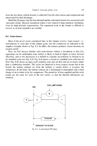
Most of the novel cycles considered later in this chapter involve ‘semi-closure’, Le.
recirculation of some part of the exhaust gases into the compressor as indicated in the
simplest example shown in Fig. 8.3. In effect, the exhaust products stream becomes an
oxygen carrier.
Here, we first discuss whether such semi-closure (which is introduced so that CO2
separation can be undertaken more easily) is likely to lead to higher or lower thermal
efficiency, and in this discussion it is helpful to consider recirculation in relation to an
air standard cycle (see Fig. 8.4). Fig. 8.4a shows a closed air standard cycle with unit air
flow; Fig. 8.4b shows an open cycle similarly with unit air flow and an air heater rather
than a combustion chamber. The cycles are identical in every respect except that in the
former the turbine exhaust air from the turbine is cooled before it re-enters the
compressor. In the latter, the turbine exhaust air is discharged to atmosphere and a fresh
charge of air is taken in by the compressor. The quantities of heat supplied and the work
output are the same for each of the two cycles, so that the thermal efficiencies are
identical.
FUEL (METHANE)
AIR I
1
COOLER
STACK
TO
EXHAUST
Fig. 8.3. A semi-closed CBT plant.