
Page 55 - Advanced Gas Turbine Cycles
P. 55
32 Advanced gas turbine cycles
reduced compared with that of the [CHT]R cycle. However, the specific work, which is
equal to the area of the cycle on the T, s diagram, is increased.
If a heat exchanger is added at low pressure ratio (Fig. 3.4b) then the mean supply
temperature is greater than that of the [cm]R cycle whereas the temperature of heat
rejection will be the same as in the [cm]R cycle. Therefore the efficiency of
the [Cmx]R cycle is greater than that of the [CHTXIR cycle.
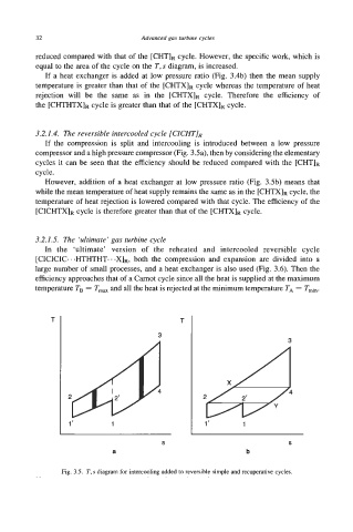
3.2.1.4. The reversible intercooled cycle [CICHTIR
If the compression is split and intercooling is introduced between a low pressure
compressor and a high pressure compressor (Fig. 3.5a), then by considering the elementary
cycles it can be seen that the efficiency should be reduced compared with the [cHT]R
cycle.
However, addition of a heat exchanger at low pressure ratio (Fig. 3.5b) means that
while the mean temperature of heat supply remains the same as in the [cm]R cycle, the
temperature of heat rejection is lowered compared with that cycle. The efficiency of the
[CICHTXIR cycle is therefore greater than that of the [cm]R cycle.
3.2.1.5. The ‘ultimate’ gas turbine cycle
In the ‘ultimate’ version of the reheated and intercooled reversible cycle
both
[CICICIC-..HTHTHT...X]R, the compression and expansion are divided into a
large number of small processes, and a heat exchanger is also used (Fig. 3.6). Then the
efficiency approaches that of a Carnot cycle since all the heat is supplied at the maximum
temperature TB = T,, and all the heat is rejected at the minimum temperature TA = Tmin.
T T
3
3
2
1‘ 1 1’ 1
S S
a b
Fig. 3.5. T,s diagram for intercooling added to reversible simple and ncuperative cycles.