
Page 51 - Advanced Gas Turbine Cycles
P. 51
28 Advanced gos turbine cycles
U and C referring to uncooled and cooled turbines in a plant, but in this chapter, all cycles
are assumed to be uncooled and these subscripts are not used.
It is implied that the states referred to in any cycle are stagnation states; but as velocities
are assumed to be low, stagnation and static states are virtually identical.
3.2. Air standard cycles (uncooled)
3.2.1. Reversible cycles
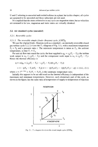
3.2.1.1. The reversible simple (Joule-Brayton) cycle, [CHT]R
We use the original Joule-Brayton cycle as a standard-an internally reversible closed
gas turbine cycle 1,2,3,4 (see the T, s diagram of Fig. 3.1), with a maximum temperature
T3 = TB and a pressure ratio r. The minimum temperature is taken as TA, the ambient
temperature, so that TI = TA.
For unit air flow rate round the cycle, the heat supplied is 4B = cp(T3 - T2), the turbine
work output is WT = c (T - T4) and the compressor work input is wc = cp(T2 - TI).
3
p
Hence the thermal efficiency is
= w/qB = [cp(T3 - T4) - cp(T2 - TdI/[Cp(T3 - T2)1
= 1 - [(T4 - Tl)/(T3 - T2)] = 1 - { [(T&Ti) - l]/[(T3/Ti) - XI} = ( UX), (3.1)
where x = r(rlyy = T2/Tl = T3/T4 is the isentropic temperature ratio.
Initially this appears to be an odd result as the thermal efficiency is independent of the
maximum and minimum temperatures. However, each elementary part of the cycle, as
shown in the fibre, has the same ratio of temperature of supply to temperature of rejection
I RESERVOIR
I TB
I 1 ATMOSPHERE
0 S
Fig. 3.1. T,s diagram for reversible closed simple cycle, [CHTIR.