
Page 56 - Advanced Gas Turbine Cycles
P. 56
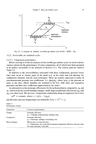
Chapter 3.  Basic gas htrbinc cycles          33


                                              qI3


                                                          \
                                                           isentropic
                                                           turbines
                                                 isentropic
                                                 compressors


                                                               S
               Fig. 3.6.  T, diagram for 'ultimate' reversible gas turbine cycle [CICIC.. .BTBT.. .XIR.
                       s
       3.2.2. Irreversible air standard cycles
       3.2.2.1.  Component pelformance
          Before moving on to the als analyses of irreversible gas turbine cycles we need to define
       various criteria for the performance of some components, all of which have been assumed
       to be perfect (reversible) in the analyses of Section 3.2.1.  The criteria used are listed in
       Table 3.1.
          In addition to the irreversibilities associated with these components, pressure losses
       (Ap) may occur  in  various parts of  the plant  (e.g.  in  the entry  and  exit ducting, the
       combustion chamber, and the heat exchanger). These are usually expressed in terms of
       non-dimensional pressure loss coefficients, t= AP/@)~, where @)m  is the pressure at
       entry  to the  duct.  (Mach numbers are assumed to be  low, with  static and  stagnation
       pressures and their loss coefficients approximately the same.)
          As alternatives to the isentropic efficiencies for the turbomachinery components,   and
       qc, which relate the overall enthalpy changes, small-stage or polytropic efficiencies ( qpT and
       qK) are often used. The pressure-temperature relationship along an expansion line is then
            p/Tz = constant, where z = ['y/(y - l)T)pTI,
       and the entry and exit temperatures are related by T3/T4 = r!")  = xT.
       Table 3.1
       Performance criteria
       Component          Criterion of performance
       Turbine            Isentropic efficiency
                           % = Enthalpy drophentropic enthalpy drop
       Compressor         Isentropic efficiency
                             = Isentropic enthalpy riselenthalpy rise
       Heat exchanger     Effectiveness (or thermal ratio)
                          E  = Temperature rise (cold side)/maximum temperature difference between entry
                          (hot side) and entry (cold side)