
Page 61 - Advanced Gas Turbine Cycles
P. 61
Chapter 3. Basic gas turbine cycles 37
Thermal efficiency
7) = NDNWmHT = [(a - x)(x - l)]/X(P - x). (3.21)
Fig. 3.8 reproduces the quantities NDNW, NDHT and v, for the example of the simple
[CHTII cycle studied by Horlock and Woods [2], in which 8 = 4.0, qc = 0.8, = 0.9,
i.e. a = 2.88, p = 3.4. The location of the maximum net work output is obvious. The
maximum cycle efficiency point is obtained by the graphical construction shown (a line
drawn tangent to NDNW at x,, from the point where the line NDHT meets the x axis at
x = p). Values of x, = 1.697 (rw = 6.368) and x, = 2.050 (re = 12.344), as calculated
from Eqs. (3.14) and (3.16), are indicated in the diagrams. The maximum thermal
efficiency is 7) = 0.315.
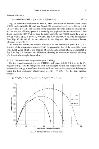
As mentioned before, the thermal efficiency for the irreversible plant [CHTIr is a
function of the temperature ratio 8 = T3/T, (as opposed to that of the reversible simple
cycle [CHT],, for which 7) is a function of x only, and pressure ratio r, as illustrated in
Fig. 3.3). Fig. 3.9 illustrates this difference, showing the irreversible thermal efficiency
77(x, 8) which is strongly &dependent.
3.2.2.3. The irreversible recuperative cycle [CkllX]~
For the closed recuperative cycle [CHTXII, with states 1,2, X, 3,4, Y as in the T, s
diagram of Fig. 3.10, the net specific work is unchanged but the heat supplied has to be
reassessed as heat 4T is transferred from the turbine exhaust to the compressor delivery air.
Using the heat exchanger effectiveness, E = (T, - T2)/(T4 - T2) the heat supplied
becomes
4Jj = Cp(T3 - Tx) = Cp(T3 - T4) -I- Cp(1 - E)(T4 - Tz), (3.22)
0.5
0.45
0.4
0.35
>
x
W 0.3
0
Y
k 0.25
i 0.2
w
x c
0.15
0.1
0.05
0
1 1.5 2 2.5 3 3.5 4 4.5
ISENTROPIC TEMPERATURE RATIO
Fig. 3.9. Thermal efficiency of [CHT], cycle.