
Page 64 - Advanced Gas Turbine Cycles
P. 64
40 Advanced gas turbine cycles
I 1
S
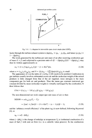
Fig. 3.1 1. T,s diagram for irreversible open circuit simple plant [CBvI.
factor through the turbine exhaust system is (ApIp)41 = (p4 - pl)/p4, and hence (pl/p4) =
1- (&/p)41*
The work generated by the turbine per unit mass of air after receiving combustion gas
of mass (1 +f) and subjected to a pressure ratio of r[ 1 - [( 1 - (A~/P)~~], may
then be written approximately as
WT 25 (1 +f)%(Cpa)12T3[1 - (1 + @/X”)l/n, (3.28)
where TJ = (~pa)d(~pg)~ and 8 = {[(~)34 - ~IX(AP/P)I/(Y~)M is small-
The appearance of n as the index of x in Eq. (3.28) needs to be justified. Combustion in
gas turbines usually involves substantial excess air and the molecular weight of the mixed
products is little changed from that of the air supplied, since nitrogen is the main
component gas for both air and products. Thus the mean gas constant (universal gas
constant divided by mean molecular weight) is virtually unchanged by the combustion. It
then follows that
The non-dimensional net work output (per unit mass of air) is then
NDNw = w/(cpa)12(T3 - TI)
= {[a( +f)/n][ 1 - (1 + S)/Y] - (x - l))/(P - l), (3.29)
1
and the ‘arbitrary overall efficiency’ of the plant ( vo) is now defined, following Haywood
[41, as
70 = w/[-rnol, (3.30)
where [ -AH0] is the change of enthalpy at temperature To in isothermal combustion of a
mass of fuel f with unit air flow (i.e. in a calorific value process). In the combustion