Page 140 - Advanced Thermodynamics for Engineers, Second Edition
P. 140

6.3 EFFICIENCY OF COMBINED CYCLE INTERNALLY REVERSIBLE HEAT              127


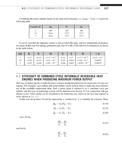
                  Comparing the power outputs based on the same total resistance, i.e. U H A H þ U C A C ¼ 2 gives the
               following table.

                                                                         _
                                             _
                            U H A H /U C AC  Q H            _ W         Q C
                                1           400            200          200
                               1/2          355.6         177.7        177.7
                                2           355.6         177.7        177.7

                  It can be seen that the optimum system is one in which the high- and low-temperature resistances
               are equal. In this case the entropy generation (per unit of work) of the universe is minimised, as shown
               in the table below.

                                                                                     P  DS
                 U H A H  _ Q H    _ Q H     DS H       _ Q C   _ Q C    DS C
                                             W                            W             W
                 U C A C  T H     T 1                   T 2    T C
                   1      0.25   þ0.333  þ4.17   10  4   0.333  þ0.5  þ4.17   10  4  þ8.34   10  4
                  1/2    0.225   þ0.333  þ6.23   10  4   0.333  0.4443  þ6.24   10  4  þ0.00125
                   2     0.225   þ0.266  þ2.48   10  4   0.266  0.4443  þ10.00   10  4  þ0.00125


               6.3 EFFICIENCY OF COMBINED CYCLE INTERNALLY REVERSIBLE HEAT
                    ENGINES WHEN PRODUCING MAXIMUM POWER OUTPUT

               One way of improving the overall efficiency of power production between two reservoirs is to use two
               engines. For example, a gas turbine and steam turbine can be used in series to make the most effective
               use of the available temperature drop. Such a power plant is referred to as a combined cycle gas
               turbine, and this type of generating system will be introduced in Section 17.1 in connection with gas
               turbine cycles. These plants can be examined in the following way, based on the two heat engines in
               series shown in Fig. 6.5.
                  In this case the product UA will be replaced by a ‘conductivity’ C to simplify the notation. Then,

                                                 _
                                                Q ¼ C H T H   T 1                           (6.18)
                                                 H
                                                 _
                                                Q ¼ C 2 T 2   T 3                           (6.19)
                                                  2
                                                 _
                                                 C
                                                Q ¼ C C T 4   T C                           (6.20)
                  Also, for E H
                                                    Q _ H  Q _  2
                                                       ¼                                    (6.21)
                                                     T 1  T 2
               and for E C
                                                    Q _  Q _
                                                      2    C
                                                       ¼                                    (6.22)
                                                    T 3  T 4
   135   136   137   138   139   140   141   142   143   144   145