
Page 54 - Advanced Thermodynamics for Engineers, Second Edition
P. 54
3.1 HEAT ENGINES 39
The work output of a Carnot cycle is defined by the areas of either a p–Vor a T–s diagram, and it can
be seen that these are finite. However, while the Carnot cycle can produce a finite work output, the
power output is zero because the rate of heat transfer to the engine across an infinitesimal temperature
difference is zero, to achieve external reversibility. This means that the Carnot efficiency defines the
maximum efficiency of a heat engine between two temperature levels. This is never achieved in practice
because all engines are, at least, significantly irreversible in the external heat transfer processes: this is
discussed in Chapter 6.
3.1.2 RANKINE CYCLE
It was shown above that the Carnot cycle for a fluid which changes phase during the working cycle
requires an expansion device which operates with a fluid with a low quality (x) at the end of the
expansion process. This creates problems in the design of the expansion device because of the amount
of liquid in the working fluid. In the case of a steam turbine there can be very bad erosion of the low-
pressure turbine blades due to water droplets in the steam, and this can reduce the reliability of the
machine. Similarly, the compression depicted in Fig. 3.3 goes from a low-quality mixture of water and
water vapour (at state 1) to saturated liquid water (at state 2). This requires careful control of state 1 to
ensure that state 2 lies on the saturated liquid line, and also a compressor that can deal with a mixture
that changes phase during the compression process.
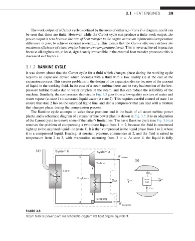
The Rankine cycle attempts to solve these problems and is the basis of all steam turbine power
plants, and a schematic diagram of a steam turbine power plant is shown in Fig. 3.5. It is an adaptation
of the Carnot cycle to remove some of the latter’s limitations. The basic Rankine cycle (see Fig. 3.6(a))
removes the problem of compressing a two-phase liquid from 1 to 2, because the fluid is condensed
right up to the saturated liquid line (state 1). It is then compressed in the liquid phase from 1 to 2, where
it is a compressed liquid. Heating, at constant pressure, commences at 2, and the fluid is raised in
temperature from 2 to 3, with evaporation occurring from 3 to 4. At state 4, the liquid is fully
(a) System b system a
3 W Turbine
(b)
Turbine
4
Boiler
Q Q in
in
Condenser Steam W net
Q out W net
plant
Q out
1
Feedpump
2
W Feedpump
FIGURE 3.5
Steam turbine power plant (a) schematic diagram (b) heat engine equivalent.