Page 348 - Advanced engineering mathematics
P. 348

328    CHAPTER 10  Systems of Linear Differential Equations
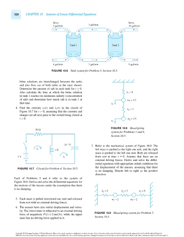
                                             Brine                                         Brine
                                             5 gal/min            3 gal/min                10 gal/min


                                                       Tank 1                    Tank 2


                                             6 gal/min            2 gal/min                9 gal/min
                                            FIGURE 10.6 Tank system for Problem 3, Section 10.5.


                        brine solutions are interchanged between the tanks
                        and also flow out of both tanks at the rates shown.
                        Determine the amount of salt in each tank for t ≥ 0.
                        Also calculate the time at which the brine solution               k  = 8
                                                                                           1
                        in tank 1 reaches its minimum salinity (concentration
                        of salt) and determine how much salt is in tank 1 at              m 1  = 1/2
                        that time.                                              y 1
                      4. Find the currents i 1 (t) and i 2 (t) in the circuit of
                                                                                          k  = 3
                                                                                           2
                        Figure 10.7 for t > 0, assuming that the currents and
                        charges are all zero prior to the switch being closed at
                        t = 0.                                                            m  = 1/2
                                                                                y 2         2
                                  50 Ω                                          FIGURE 10.8 Mass/spring
                                                                                system for Problems 5 and 6,
                                                                                Section 10.5.


                                                   10 –3  F         7. Refer to the mechanical system of Figure 10.9. The
                                  i 1        1 H                       left mass is pushed to the right one unit, and the right
                                                                       mass is pushed to the left one unit. Both are released
                       5 V                         i 2                 from rest at time t = 0. Assume that there are no
                                                                       external driving forces. Derive and solve the differ-
                                                                       ential equations with appropriate initial conditions for
                                                                       the displacement of the masses, assuming that there
                       FIGURE 10.7 Circuit for Problem 4, Section 10.5.
                                                                       is no damping. Denote left to right as the positive
                                                                       direction.
                     Each of Problems 5 and 6 refer to the system of
                     Figure 10.8. Derive and solve the differential equations for
                     the motions of the masses under the assumption that there
                     is no damping.
                                                                           k  = 8      k  = 5     k 3  = 8
                                                                                       2
                                                                           1
                      5. Each mass is pulled downward one unit and released      m  = 2     m  = 2
                                                                                             2
                                                                                  1
                        from rest with no external driving forces.
                      6. The masses have zero initial displacement and veloc-
                        ity. The lower mass is subjected to an external driving
                                                                      FIGURE 10.9 Mass/spring system for Problem 7,
                        force of magnitude F(t) = 2sin(3t), while the upper
                                                                      Section 10.5.
                        mass has no driving force applied to it.


                      Copyright 2010 Cengage Learning. All Rights Reserved. May not be copied, scanned, or duplicated, in whole or in part. Due to electronic rights, some third party content may be suppressed from the eBook and/or eChapter(s).
                      Editorial review has deemed that any suppressed content does not materially affect the overall learning experience. Cengage Learning reserves the right to remove additional content at any time if subsequent rights restrictions require it.

                                   October 14, 2010  20:32  THM/NEIL   Page-328        27410_10_ch10_p295-342
   343   344   345   346   347   348   349   350   351   352   353