
Page 118 - Advanced thermodynamics for engineers
P. 118
104 CHAPTER 5 RATIONAL EFFICIENCY OF POWER PLANT
Equation (5.21) shows that the irreversibility of the expansion process reduces the net work
significantly by (1) increasing the amount of exergy rejected and (2) increasing the irreversibility of the
cycle. The rational efficiency of this cycle is
ðb 3 b 4 Þ T 0 ðs 3 s 3s Þ
h ¼ 1 (5.22)
R
b 2 b 3
The irreversible cycle can be seen to be less efficient than the reversible one by comparing Eqns
(5.20) and (5.22). In the case shown b 2 b 1 is the same for both cycles, but b 3 b 4 > b 3s b 4 , and in
addition the irreversibility T 0 (s 3 s 3s ) has been introduced.
5.3 RANKINE CYCLE
It was stated above that the efficiency of a cycle is often evaluated neglecting the irreversibility of the
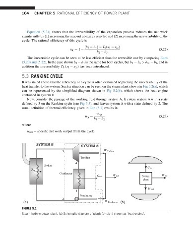
heat transfer to the system. Such a situation can be seen on the steam plant shown in Fig 5.2(a), which
can be represented by the simplified diagram shown in Fig 5.2(b), which shows the heat engine
contained in system B.
Now, consider the passage of the working fluid through system A. It enters system A with a state
defined by 3 on the Rankine cycle (see Fig 5.3), and leaves system A with a state defined by 2. The
usual definition of thermal efficiency given in Eqn (5.1) results in
w net
h ¼ (5.23)
th
h 3 h 2
where
w net ¼ specific net work output from the cycle.
system b system a
3 W Turbine
Turbine
4
Boiler
Q in
Q in
Condenser
Q out W net Steam W net
plant
Q out
1
Feedpump
2
(a) W Feedpump (b)
FIGURE 5.2
Steam turbine power plant. (a) Schematic diagram of plant; (b) plant shown as ‘heat engine’.