Page 124 - Advanced thermodynamics for engineers
P. 124

110    CHAPTER 5 RATIONAL EFFICIENCY OF POWER PLANT


             parameters for the steam plant if (a) the isentropic efficiency of the turbine is 80%; (b) the isentropic
             efficiency of the feed pump is 70%; (c) if the efficiency of the components is the combination of those
             given in (a) and (b). Assume that t 0 ¼ 81.3 C.

                Solution
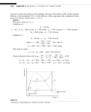
                This cycle is shown in Fig 5.5.
                Conditions at 6

                                                p 6 ¼ 0:5 bar;


               t s ¼ 81:3 C; h g ¼ 2645 kJ kg; h f ¼ 340 kJ kg; s g ¼ 7:593 kJ kg K; s f ¼ 1:091 kJ kg K:

                                     h 6 ¼ 2645 kJ=kg; s 6 ¼ 7:593 kJ=kg K:
                Conditions at 5
                                     p 5 ¼ 20 bar; s 5 ¼ s 6 ¼ 7:593 kJ kg K:

                                                 7:593   7:431

                                 Hence; t 5 ¼ 500 þ            100 ¼ 560 C;
                                                 7:701   7:431
                                  h 5 ¼ 3467 þ 0:6  ð3690   3467Þ¼ 3601 kJ=kg:
                Work done by turbine,
                                   w T ¼ h 5   h 6 ¼ 3601   2645 ¼ 956 kJ=kg K:

                                                 w net  w T þ w P  956   2:0
                Thermal efficiency of the cycle is h ¼  ¼       ¼            ¼ 0:292
                                             th
                                                  q in  h 5   h 2  3601   342:0
                        b 5 ¼ h 5   T 0 s 5   a 0 ¼ 3601   354:3   7:593   a 0 ¼ 910:8   a 0 kJ=kg;
                        b 2 ¼ h 2   T 0 s 2   a 0 ¼ 342:1   354:3   1:091   a 0 ¼ 44:4   a 0 kJ=kg:


                              Temperature, T                    5


                                             Q
                                             in
                                    3                 4          W T


                                  2
                                    W P
                                  1                               6'
                                                              6
                                         Q out                      saturated vapour
                                                                    line
                                   saturated liquid
                                   line
                                                               Entropy, S
             FIGURE 5.5
             Temperature–entropy diagram for Rankine cycle with superheat.
   119   120   121   122   123   124   125   126   127   128   129