
Page 367 - Advanced thermodynamics for engineers
P. 367
356 CHAPTER 16 RECIPROCATING INTERNAL COMBUSTION ENGINES
Directinjectiondiesel engines (shownschematically inFig. 16.5(a), and in more detail in Fig. 16.5(c)
and (d)) used to dominate the larger size range. However, the introduction of higher injection pressures,
and in particular common-rail injection, has resulted in most small vehicular diesel engines (say
3
400 cm /cylinder) being di. Nearly all truck diesel engines are di, as are those for rail and marine
applications. The bottom limit of size for di diesel engines is reducing all the time and four cylinder
engines as small as 1.6 L are available for van and car applications. The largest di diesel engines, with
bores as large as 1000 mm, have quiescent combustion chambers, in which there is no organised air
motion. The mixing of the fuel and air is achieved by the multiple fuel jets entraining air into themselves
and bringing about the necessary mixing. More than six holes might be used in the fuel injector nozzle
to give good utilisation of the air in the chamber. The relatively low engine speed of large engines allows
sufficient time for combustion to occur. As the engine bore size reduces so the engine rotational speed
increases, and the time available for combustion becomes shorter. Also the appropriate size of injector
hole reduces, until it reaches the limit that can be achieved by production techniques (around 0.18 mm
diameter) The increased engine speed, and reduced time for mixing, requires that the rate of mixing of
the fuel and air is enhanced above that which can be achieved using a quiescent combustion chamber.
The mixing rate can be increased by imparting air motion to the charge, and this is done in the form of
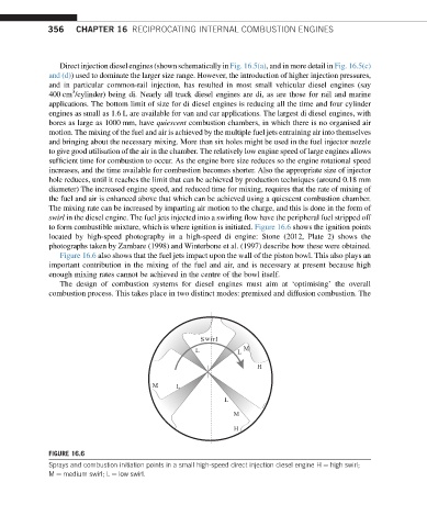
swirl in the diesel engine. The fuel jets injected into a swirling flow have the peripheral fuel stripped off
to form combustible mixture, which is where ignition is initiated. Figure 16.6 shows the ignition points
located by high-speed photography in a high-speed di engine: Stone (2012, Plate 2) shows the
photographs taken by Zambare (1998) and Winterbone et al. (1997) describe how these were obtained.
Figure 16.6 also shows that the fuel jets impact upon the wall of the piston bowl. This also plays an
important contribution in the mixing of the fuel and air, and is necessary at present because high
enough mixing rates cannot be achieved in the centre of the bowl itself.
The design of combustion systems for diesel engines must aim at ‘optimising’ the overall
combustion process. This takes place in two distinct modes: premixed and diffusion combustion. The
S wirl
L L M
H
M L
L
M
H
FIGURE 16.6
Sprays and combustion initiation points in a small high-speed direct injection diesel engine H ¼ high swirl;
M ¼ medium swirl; L ¼ low swirl.