
Page 369 - Advanced thermodynamics for engineers
P. 369
358 CHAPTER 16 RECIPROCATING INTERNAL COMBUSTION ENGINES
where
¼ partial pressure of oxygen
p O 2
P ¼ rate of preparation of fuel by mixing
R ¼ rate of reaction
m i ¼ mass of fuel injected
m u ¼ mass of fuel unburned
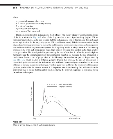
These equations result in instantaneous ‘heat release’ (the energy added by combustion) patterns
of the form shown in Fig. 16.7. One of the diagrams has a short ignition delay (higher CN, or
operating temperature), and it can be seen that the instantaneous rate of heat release does not reach
such a high level as for the long delay (lower CN, or cold conditions). This is because the time for the
physical and chemical processes to enable the fuel to reach a hypergolic state is less, and consequently
less fuel is available for spontaneous ignition. The long delay results in a large amount of fuel burning
spontaneously, with high temperature rises, high rates of pressure rise (dp/da) and a high level of
noise generation. The initial period is governed by the rate of reaction, R. After the premixed phase
has taken place the temperatures inside the combustion chamber are high and the rate of reaction is
much faster than the rate of preparation, P. At this stage, the combustion process is governed by
Eqn (16.16b), which models a diffusion process. During this process, the rate of combustion is
controlled by the rate at which the fuel and air mix, and in this phase the hydrocarbon fuel in the centre
of the jet is burning in insufficient oxygen. The fuel pyrolyses and forms the precursors of the carbon
particles produced in the exhaust system. It is important to mix the burning fuel with the air at the
appropriate rate to ensure that the carbon produced during the combustion process is consumed before
the exhaust valve opens.
short ignition delay
long ignition delay
Rate of heat release
α inj Crankangle, α
FIGURE 16.7
Effect of ignition delay on rate of heat release diagram.