
Page 392 - Advanced thermodynamics for engineers
P. 392
382 CHAPTER 17 GAS TURBINES
There are two types of gas turbine – open cycle and closed cycle. By far the greatest proportion of
gas turbines built is the open cycle type. The closed cycle gas turbine requires a cooler (cf. the
condenser of a steam turbine) to enable the working fluid to circulate through the system – and this
allows exotic fluids, e.g. mercury, to be considered, as done in a nuclear cycle.
17.1 THE GAS TURBINE CYCLE
The gas turbine is similar to the internal combustion engine inasmuch as it is not usually a ‘heat
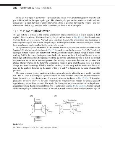
engine’. The exception to this is the closed cycle gas turbine shown in Fig. 17.1(a). In this device the
working fluid, air or a similar ‘perfect gas’, circulates through the components and undergoes a
thermodynamic cycle. Much of the analysis of gas turbine cycles is based on the closed cycle, but the
basic conclusions can be applied to the open cycle engine.
The gas turbine cycle is referred to as the Joule or Brayton cycle, and this was discussed briefly in
Section 3.2.5: the basic cycle is shown in Fig. 17.2 (which is exactly the same as Fig 3.17). The closed
cycle gas turbine consists of a compressor, turbine, heater and cooler. Hence energy is added to the
working fluid in the heater (analogous to the boiler of a steam turbine). A major difference between
the energy addition and rejection processes of the gas turbine and steam turbine is that in the former
the processes are at almost constant pressure but varying temperature (because the gas does not
change phase) whereas in the latter the temperature range is quite small because there is a phase
change to contain the energy. This has an effect on the cycle efficiency and the work ratio. The work
done in the cycle is depicted by the areas of the p–V and T–s diagrams in the case of reversible
processes.
The most common type of gas turbine is the open cycle one in which the air is used to burn the
fuel. The air does not undergo a cycle and there are mass transfers across the engine boundaries
hence the device is not a heat engine. A schematic diagram is shown in Fig. 17.1(b). This engine
produces a net power output via the shaft connecting the compressor and turbine: the exhaust gas is at
approximately atmospheric pressure. The ‘cycle’ for this engine is the same as for the closed cycle one,
except the working fluid is not cooled from 4 to 1, and is shown in Fig. 17.2(a) and (b). Another variant
of the open cycle gas turbine is that used in aircraft, when often the requirement is to produce a jet of
(a) (b)
Heater Combustion
Fuel
chamber
Air Exhaust
2 3 1 2 3 4
C T C T
Power Power
1 4
Precooler
FIGURE 17.1
(a) Closed cycle gas turbine. (b) Open cycle gas turbine.