
Page 393 - Advanced thermodynamics for engineers
P. 393
17.1 THE GAS TURBINE CYCLE 383
(a) (b)
Constant
3 3
pressure 2
Temperature, T 2 Pressure, p Isentropic
4
4
1
Isentropic Constant
1 pressure
Specific entropy, s Volume, V
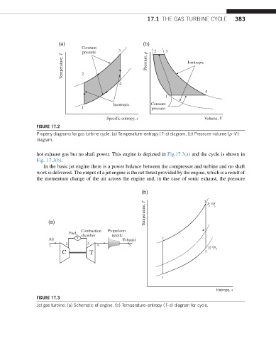
FIGURE 17.2
Property diagrams for gas turbine cycle. (a) Temperature–entropy (T–s) diagram. (b) Pressure–volume (p–V )
diagram.
hot exhaust gas but no shaft power. This engine is depicted in Fig.17.3(a) and the cycle is shown in
Fig. 17.3(b).
In the basic jet engine there is a power balance between the compressor and turbine and no shaft
work is delivered. The output of a jet engine is the net thrust provided by the engine, which is a result of
the momentum change of the air across the engine and, in the case of sonic exhaust, the pressure
(b) 3
Temperature, T p =p 3
2
(a)
Combustion Propulsion 4
Fuel
chamber nozzle
Air Exhaust 2
2 3
1 4 5 p =p 5
1
C T 5
1
Entropy, s
FIGURE 17.3
Jet gas turbine. (a) Schematic of engine. (b) Temperature–entropy (T–s) diagram for cycle.