
Page 394 - Advanced thermodynamics for engineers
P. 394
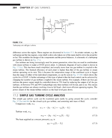
384    CHAPTER 17 GAS TURBINES


                                    Propellor              Combustion
                                                      Fuel
                                               Air         chamber
                                                                   Exhaust
                                                     2       3
                                              1                   4
                                                    C         T
                                             Power


             FIGURE 17.4
             Turboprop aircraft gas turbine.


             difference across the engine. These engines are discussed in Section 17.3. In certain variants, e.g. the
             turboprop and the fan engines, some shaft work is also taken out of the main shaft to drive the propeller
             or fan. This modifies the design of the components and the power balances. A schematic of a turboprop
             gas turbine is shown in Fig. 17.4.
                Gas turbines are being increasingly used for power generation, when they are used in combination
             with steam turbines to make a CCGT power plant. A schematic diagram of such a plant is shown in
             Fig. 17.5(a). This has been much simplified, and usually more than one gas turbine is coupled to the
             steam turbine. The thermal efficiency of such plant is higher than that of the gas turbine or steam
             turbine operating on its own. This is because the temperature range of the combined cycle is bigger
             than the range of either of the individual components, as can be seen in Fig. 17.5(b) which shows the
             cycles for a CCGT. A further advantage of this type of plant is that the load control can be achieved by
             changing the number of gas turbines coupled to the steam turbine. For example, if there are four gas
             turbines the power output might be controlled down to 75% load by reducing the output of all the gas
             turbines. At between 75% and 50% load perhaps only three turbines will be run, and so on. This means
             that the gas turbines are always working close to full load – their most efficient operating regime. The
             power output of the steam turbine reduces as the load level goes down.

             17.2 SIMPLE GAS TURBINE CYCLE ANALYSIS
             The simple gas turbine cycle can be examined quite easily by going around the cycle; consider
             Fig. 17.2(a) and (b) for the closed cycle gas turbine, and assuming unit mass of fluid:
                Compressor work, w 12

                                       w 12 ¼  h 2   h 1 ¼ c p T 2   T 1                  (17.1)
                Turbine work, w 34

                                        w 34 ¼  h 4   h 3 ¼ c p T 3   T 4                 (17.2)
                The heat supplied (at constant pressure), q 23 is


                                              q 23 ¼ c p T 3   T 2                        (17.3)