
Page 398 - Advanced thermodynamics for engineers
P. 398
388 CHAPTER 17 GAS TURBINES
1
w net ¼ c p T 3 1 c p T 1 fs r 1g: (17.14)
s r
The maximum net work is obtained when vw net /vs r ¼ 0, hence
vw net 1
¼ c p T 3 2 c p T 1 ¼ 0; (17.15)
vs r s
r
giving
1=2
2 T 3 T 3 p ffiffiffi
s ¼ or s r ¼ ¼ g; (17.16)
r
T 1 T 1
where g is the ratio of the maximum to minimum temperature. Now the isentropic ratio, s r ¼ T 2 /T 1 ¼
T 3 /T 4 . Thus, for maximum net work T 2 T 3 ¼ g; but by definition, g ¼ T 3 /T 1 and hence T 2 ¼ T 4 .
T 1 T 4
This means that in the cycle which produces the maximum net work the temperature of the gas
leaving the compressor (T 2 ) is equal to the temperature of the gas leaving the turbine (T 4 ). An effect of
this is that a heat exchanger cannot be used in this cycle (see Section 17.2.2).
17.2.1 EFFECT OF TEMPERATURES FOR DELIVERING AND REJECTING ENERGY
In the previous section it was shown that the cycle efficiency can approach the Carnot efficiency: this
occurs when an infinitesimal quantity of energy is added at ‘constant temperature’. If the working fluid
is considered to be a perfect gas (i.e. constant specific heats) then the energy levels in the cycle are
linearly related to the temperature of the gas. This enables the following analysis to be performed. A
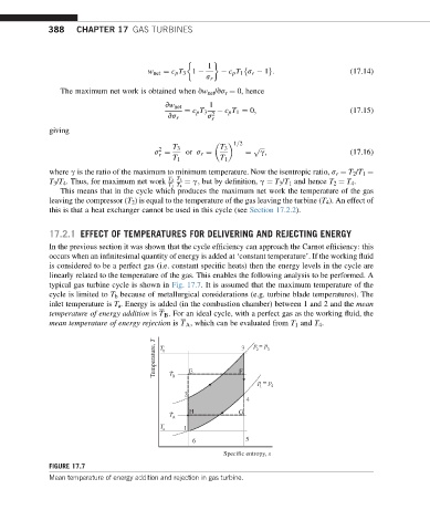
typical gas turbine cycle is shown in Fig. 17.7. It is assumed that the maximum temperature of the
cycle is limited to T b because of metallurgical considerations (e.g. turbine blade temperatures). The
inlet temperature is T a . Energy is added (in the combustion chamber) between 1 and 2 and the mean
temperature of energy addition is T B . For an ideal cycle, with a perfect gas as the working fluid, the
mean temperature of energy rejection is T A , which can be evaluated from T 1 and T 4 .
Temperature, T T b - 3 p = p 3
2
F
E
T
B
p = p
1 4
2
4
- H G
T A
T
a 1
6 5
Specific entropy, s
FIGURE 17.7
Mean temperature of energy addition and rejection in gas turbine.