
Page 427 - Advanced thermodynamics for engineers
P. 427
17.4 COMBUSTION IN GAS TURBINES 417
Primary hole Liner Cooling slot
Fuel Igniter
nozzle
Outer annulus
Dilution Nozzle
Diffuser Primary Secondary zone zone
zone
Snout Inner annulus
Swirler
Intermediate
hole
Dilution hole
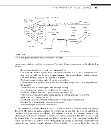
FIGURE 17.25
Section through aero gas turbine annular combustion chamber.
engine costs, efficiency and the environment. The basic design requirements can be classified as
follows:
• High combustion efficiency at all operating conditions.
• Low levels of unburned hydrocarbons and carbon monoxide, low oxides of nitrogen at high
power and no visible smoke for land-based systems. (Minimized pollutants and emissions.)
• Low pressure drop. Three to four percent is common.
• Combustion must be stable under all operating conditions.
• Consistently reliable ignition must be attained at very low temperatures, and at high altitudes
(for aircraft).
• Smooth combustion, with no pulsations or rough burning.
• A low temperature variation for good turbine life requirements.
• Useful life (thousands of hours), particularly for industrial use.
• Multi-fuel use. Characteristically natural gas and diesel fuel are used for industrial
applications and kerosene for aircraft.
• Length and diameter compatible with engine envelope (outside dimensions).
• Designed for minimum cost, repair and maintenance.
• Minimum weight (for aircraft applications).
The combustion chamber, shown in Fig. 17.25, has a number of elements which will now be
described. The outer, air, casing contains the compressed air and bears its load. On entering the
chamber the air passes through the diffuser, which slows the air from the compressor outlet velocity,
which might reach 150 m/s or higher, to one that will sustain combustion. The diffuser also converts
the dynamic head of the air into pressure, and delivers a smooth stable flow to the main chamber. This
region also distributes the airflow between the primary air entering the snout and the secondary air
entering the inner and outer annuli. After the diffuser, liquid fuel is injected, in droplet form, into the